Product Core Brief
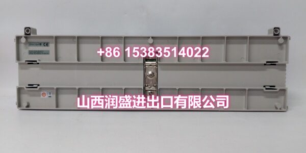
- Model: 1C31222G01
- Brand: Emerson (Ovation System)
- Series: Ovation DCS Digital Output PMOD Subsystem
- Core Function: High-power relay output base assembly that houses the relay kit and interfaces the Ovation controller’s digital output logic module to high-voltage/high-current field loads.
- Product Type: DO PMOD Relay Output Base (High-Power)
- Key Specs: 12 Channels | 150VDC @ 10A (Form X) | KUEP Electromechanical Style
- Condition: New Original / New Surplus
Key Technical Specifications
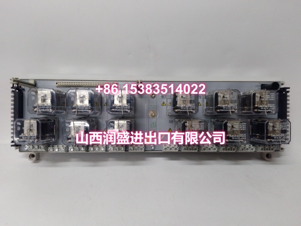
- Module Type: DO PMOD Relay Output Base Assembly (High-Power)
- Number of Channels: 12 relay outputs per base
- Relay Style: KUEP electromechanical
- Compatible Relay Kits: 5A26458G01 (Form C), 5A26458G02 (Form X), 5A26458G03 (Project-specific)
- Rated Load Capacity (Form X): 150VDC @ 10A per channel
- Rated Load Capacity (Form C): 250VAC/DC @ 5A per channel (typical)
- Dielectric Isolation: 2200V AC/DC (relay contacts to logic)
- Auxiliary Power Consumption: 23.45W typical / 30.1W maximum (with 5A26458G01 Form C kit)
- Logic Module Power: 4.56W typical / 4.75W maximum (supplied by 1C31219G01 logic module)
- Operating Temperature: 0℃ to 60℃ (32℉ to 140℉)
- Compatible Logic Module: 1C31219G01 (Ovation Relay Output Logic Module)
- Complete Assembly Part Numbers: 5A26458G05 (1C31219G01 + 1C31222G01 with Form C kit)
Product Introduction
This high-power relay output base is the field-side interface component of the Emerson Ovation digital output PMOD subsystem. It mounts directly into the Ovation I/O rack and accepts the 1C31219G01 relay output logic module, providing 12 channels of electromechanical relay switching for controlling high-power field devices — motor starters, solenoid valves, circuit breaker trip coils, and alarm annunciators in power generation and heavy process industries.
The KUEP-style relay architecture is the key differentiator here. Unlike solid-state DO modules limited to low-voltage signaling, this base paired with a Form X relay kit (5A26458G02) handles up to 150VDC at 10A per channel — enough to directly trip a medium-voltage breaker or drive a large contactor coil without an intermediate interposing relay. That eliminates a whole layer of wiring, panel space, and failure points. If your application demands direct high-power switching from the DCS, this is the hardware you spec.
QA & Testing SOP
Relay bases fail mechanically long before they fail electronically. Our validation protocol targets the wear points:
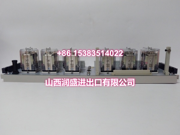
- Physical & Anti-Counterfeit Inspection: We verify the OEM chassis, check for authentic Emerson labeling, and inspect the relay socket contacts for corrosion, pitting, or spring fatigue. Bent or oxidized socket pins are the most common cause of intermittent channel failure in surplus relay bases.
- Socket Continuity & Pinout Verification: Using a precision multimeter, we verify continuity from each of the 12 channel terminals through the socket to the backplane connector. We also check for shorts between adjacent channels — a manufacturing defect or shipping damage that can cause cross-channel activation.
- Relay Kit Seating & Lock Test: We install a compatible relay kit (Form C or Form X) and verify the mechanical locking mechanism engages properly. A loose relay kit will vibrate out during operation, especially in turbine hall environments with high mechanical vibration.
- Load-Bank Switching Test: The base is mounted on an OEM test rack with the 1C31219G01 logic module. We cycle each of the 12 channels under rated load to verify clean make/break operation, measure contact resistance (must be <50mΩ), and confirm the dielectric isolation holds at 2200V AC/DC.
- Auxiliary Power Draw Verification: We measure the base’s auxiliary power consumption under full load to confirm it stays within the 30.1W maximum spec. Excessive draw indicates a shorted coil or failing relay.
- Anti-Static Packaging: After validation, the base is sealed in industrial-grade ESD shielding bags with relay socket protectors installed to prevent dust contamination and pin damage during transit.
Installation Pitfalls & Guide
This is a high-power switching component. Wiring mistakes here don’t just cause bad data — they can weld contacts, trip breakers, or start fires.
- ❗ Form C vs. Form X Kit Mismatch: The base accepts multiple relay kits, but Form C (5A26458G01) and Form X (5A26458G02) have different contact configurations and load ratings. Installing a Form C kit when your field wiring expects Form X NO/NC logic will cause incorrect device operation. Always verify the relay kit part number matches your I/O wiring diagram before installation.
- ❗ Exceeding the 10A DC Rating: The 150VDC @ 10A rating is for resistive loads only. Inductive loads (solenoid coils, motor starters) generate massive back-EMF spikes during switching that can exceed the relay’s interrupt rating and weld the contacts closed. Always install flyback diodes or RC snubbers across inductive loads.
- ❗ Auxiliary Power Overload: With all 12 channels energized, the base draws up to 30.1W. If you’re stacking multiple relay bases in a single rack, verify the rack’s auxiliary power supply can handle the cumulative draw. An overloaded aux supply will cause all relay channels to chatter or drop out.
- ❗ Contact Arcing in DC Applications: DC arcs are significantly harder to extinguish than AC arcs. If you’re switching DC loads above 48V, ensure you’re using the Form X kit rated for 150VDC and that your wiring uses properly rated DC-rated cable and terminal blocks.
Replacement Procedure:
- Pre-Install: Back up the Ovation controller logic. Document all field wiring connections on the terminal block. Verify the replacement base matches the relay kit type (Form C or Form X) installed in your system.
- Removal: De-energize the field loads connected to the relay outputs. Disconnect all field wiring from the terminal block. Release the base locking mechanism and carefully pull the base straight out of the rack.
- Install: Seat the new base firmly into the rack slot and engage the locking mechanism. Install the compatible relay kit and verify the mechanical lock engages. Reconnect all field wiring per your documented terminal assignments.
- Power-On Test: Restore auxiliary power and verify the base’s status indicators. Use the Ovation controller to individually cycle each of the 12 channels and verify the corresponding field device operates correctly. Measure contact voltage drop under load to confirm clean switching.
Technical FAQ
What’s the difference between 1C31222G01 and 1C31223G01? The 1C31222G01 is the high-power KUEP-style base (12 channels, up to 150VDC @ 10A with Form X kit). The 1C31223G01 is the G2R-style base, which is a smaller, lower-power relay base typically used for lighter switching loads. They are not interchangeable — the relay kits and socket pinouts are different. Always match the base to your existing relay kit type.
Can I use this base without the 1C31219G01 logic module? No. The 1C31222G01 is just the base assembly — it provides the relay sockets, terminal blocks, and backplane interface. The 1C31219G01 logic module plugs into the base and provides the actual digital output logic that drives the relay coils. You need both components to form a complete relay output channel.
What happens if a relay contact welds shut? The KUEP relays are mechanically robust, but welded contacts are a known failure mode when switching inductive loads above the interrupt rating. The Ovation controller can detect a welded contact through its diagnostic feedback circuit (if configured), but physical inspection and replacement of the relay kit is required. This is why we recommend keeping spare relay kits (5A26458G01/G02) in stock alongside the base.
Is this base hot-swappable? The base itself is not designed for hot-swapping under load. Removing the base while relay contacts are carrying current will arc and can damage the terminal blocks. The Ovation system supports online replacement of the logic module (1C31219G01), but the base should only be replaced during a planned maintenance window with all field loads de-energized.
Do you supply the complete assembly or just the base? We can supply the 1C31222G01 base alone, or the complete assembly (1C31219G01 logic module + 1C31222G01 base + relay kit) as part number 5A26458G05 (Form C) or 5A26458G02 equivalent (Form X). For MRO stocking, we recommend keeping both the base and spare relay kits on hand — the base rarely fails, but relay contacts wear out over time.
Need the compatible 1C31219G01 logic module and 5A26458G02 Form X relay kit specs for a complete assembly quote? I can pull those up for you.