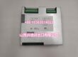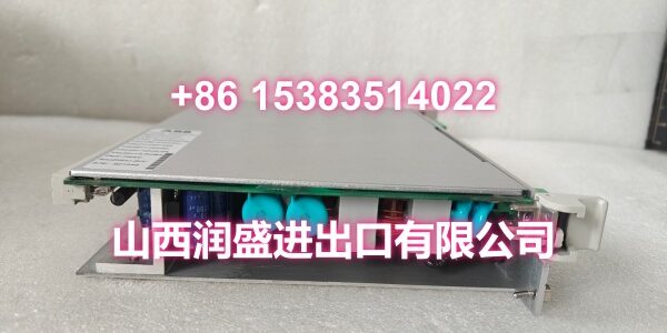
Product Core Brief
- Model: 500PSM03 (1MRB150038R1 / 894-030375D / 136-011100H)
- Brand: ABB
- Series: ABB AC 500 Series PLC Platform
- Core Function: System power supply module providing stable 24VDC backplane power for CPU, I/O, and communication modules in the AC 500 rack.
- Product Type: Rack-Mount Power Supply Module
- Key Specs: 24VDC Output | 100W Output Power | Redundant Operation Support | 85–264VAC Wide-Range Input | -25°C to +60°C Operating Range
- Note: Condition: New Original (New Surplus). Assembly references 894-030375D and 136-011100H match installed-base tracking for procurement.
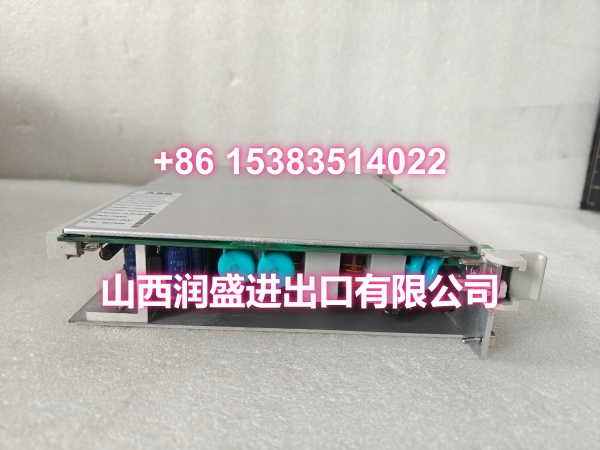
Key Technical Specifications
| Parameter | Value |
|---|---|
| Manufacturer Part Number | 1MRB150038R1 |
| Assembly References | 894-030375D / 136-011100H |
| Device Model | 500PSM03 |
| Functional Type | System Power Supply Module |
| Parent System | ABB AC 500 Series PLC |
| Input Voltage (AC) | 85–264 VAC, 50/60 Hz (wide-range, global deployment) |
| Input Voltage (DC) | 24–110 VDC (supports battery or DC bus supply) |
| Input Current | 1.5–3 A typical (AC input, varies with load) |
| Output Voltage | 24 VDC (regulation accuracy ±1%) |
| Output Power | 100 W typical (drives approximately 8–12 I/O modules depending on load) |
| Ripple Noise | ≤30 mV |
| Efficiency | ≥90% |
| Electrical Isolation | 500 VAC input-to-output isolation |
| Protection Functions | Overvoltage, undervoltage, overload, short-circuit, surge protection with auto-recovery |
| Redundancy | Supports parallel redundant configuration (primary-backup automatic failover) |
| Mounting Method | Plug-in module for AC 500 system rack power slot, mates with backplane bus |
| Operating Temperature | -25°C to +60°C |
| Protection Rating | IP20 (control cabinet installation) |
| Status Indicators | Power (green), Fault (red), Redundancy (yellow) LEDs |
| Condition | New Original (New Surplus) |
Product Introduction
The ABB 500PSM03 (order code 1MRB150038R1, assembly references 894-030375D / 136-011100H) is a system power supply module for the ABB AC 500 series PLC platform. It converts incoming AC or DC power into regulated 24VDC delivered through the backplane bus to power the CPU, I/O modules, and communication modules in the rack—acting as the electrical heart of the AC 500 control system.
Designed for process industries where power continuity is critical (energy, chemical, manufacturing), the module features a wide-range 85–264VAC input that tolerates global grid variations and transient fluctuations. Built-in overvoltage, undervoltage, overload, and short-circuit protection with auto-recovery prevents nuisance trips from grid disturbances. The 500 VAC input-to-output isolation blocks interference feedback from the field side into the power stage.
For sites running redundant power configurations, two 500PSM03 modules can be connected in parallel on the backplane bus with independent input supplies, achieving primary-backup automatic failover without additional wiring—the system manages the switching logic internally. Front-panel LEDs (Power, Fault, Redundancy) provide at-a-glance health status, and voltage/current data can be monitored through Control Builder AC 500 software for predictive maintenance.
The assembly identifiers 894-030375D and 136-011100H are critical for procurement matching—these ensure the replacement module’s hardware revision and firmware are compatible with your installed base, avoiding integration issues that can arise from undocumented revision changes.
QA & Testing SOP
Every unit goes through a structured verification process before shipment:
- Visual Inspection: Check for burnt components, swollen capacitors, corrosion on the backplane connector pins, and physical damage to the front-panel terminal block. Verify that all terminal screws are present and undamaged.
- Backplane Connector Verification: Inspect the backplane power connector for bent or pushed-out pins. A poor backplane connection is the most common cause of intermittent power loss and rack-wide module faults.
- Input-to-Output Isolation Test: Using a megohmmeter, verify the 500 VAC galvanic isolation between the input terminals and the output/backplane side. This catches latent insulation breakdown that can cause ground faults in electrically noisy environments.
- Output Voltage & Load Regulation Test: Apply rated input voltage and verify the output is 24VDC ±1%. Connect a resistive load and verify the voltage remains within spec under load. This confirms the regulation circuitry and output capacitors are healthy.
- Protection Function Verification: Where test infrastructure allows, simulate overvoltage, undervoltage, and short-circuit conditions to verify the module’s protection circuits trigger correctly and auto-recover when the fault is cleared.
- Anti-Counterfeit & Packaging: Verify authenticity markings on the PCB and label. Each unit is shipped in anti-static packaging with desiccant to prevent moisture damage during transit.
Installation Pitfalls & Guide
Replacing a system power supply module carries higher risk than swapping an I/O module—a mistake here can take down the entire rack.
❗ Redundant Pair Matching: If your system runs two 500PSM03 modules in redundancy, both modules should be the same hardware revision. Mixing revisions (e.g., replacing only one side with a different assembly code) can cause unequal load sharing or failover timing issues. Verify the assembly reference (894-030375D / 136-011100H) matches your existing module before installation.
❗ Input Power Phasing for Redundant Systems: In redundant configurations, each module’s input must be fed from independent power sources (e.g., two separate AC feeds or one AC and one DC battery bus). Feeding both modules from the same source defeats the purpose of redundancy—a single upstream fault will still take down both supplies.
❗ Terminal Torque Specification: Loose input power terminals cause arcing and heat buildup, which can melt the terminal block or cause intermittent input loss. Use a calibrated torque screwdriver to tighten input terminals to the manufacturer’s specification (typically 0.5–0.6 N·m for these terminal blocks).
❗ Hot-Swap Precautions: The AC 500 platform supports hot-swapping for power modules when properly configured in system parameters. However, removing a power module while the rack is under full load can cause a momentary voltage dip on the backplane bus. If the remaining module is near its capacity limit, this dip may trip undervoltage protection on sensitive I/O modules. Verify the remaining module can carry the full rack load before hot-swapping.
4-Step Replacement Guide:
- Pre-install: Document the input wiring configuration (AC or DC, terminal assignments), verify the assembly reference matches your installed base, and confirm the remaining power module (if redundant) can carry the full rack load. Back up your Control Builder AC 500 project.
- Removal: If hot-swapping, ensure the redundant partner module’s Power LED is solid green before proceeding. Disconnect input power wires from the old module’s terminal block (label each wire). Release the front locking hardware and slide the module straight out.
- Install: Slide the new module firmly into the power slot, ensuring the backplane connector seats fully. Secure the front locking hardware. Reconnect input power wires to the correct terminals per your labels (L1, N, PE for AC; +, -, PE for DC).
- Power-on Test: Apply input power. Verify the Power LED illuminates green and the Fault LED remains off. In redundant configurations, verify the Redundancy LED indicates the correct primary/backup status. Monitor the backplane voltage through Control Builder AC 500 software to confirm stable 24VDC output under load.
Technical FAQ
1. What’s the difference between 500PSM03 and 500PSM03A? The 500PSM03 and 500PSM03A are functionally equivalent power supply modules for the AC 500 platform. The “A” suffix typically indicates a minor hardware revision or assembly update. Both provide 24VDC output at 100W with redundant operation support. For replacement purposes, they are generally interchangeable, but it’s best practice to match the assembly reference (894-030375D / 136-011100H) to your installed base to ensure full compatibility.
2. Can I use this module with INFI 90 racks? The 500PSM03 is primarily designed for the AC 500 series PLC platform. Some INFI 90-based control cabinets may accept this module depending on the rack type and backplane configuration, but compatibility is not guaranteed. Verify the rack model and backplane pinout before attempting installation in an INFI 90 system.
3. How do I set up redundant operation with two 500PSM03 modules? Redundant configuration requires no additional wiring beyond the standard installation. Install two modules in the rack’s power slots, connect each module’s input to an independent power source (e.g., two separate AC feeds), and the modules automatically share the load through the backplane bus. The system manages primary-backup switching internally. Verify redundancy status via the front-panel Redundancy LED or through Control Builder AC 500 software.
4. What does the Fault LED indicate? The red Fault LED illuminates when the module detects an input abnormality (overvoltage, undervoltage, input loss) or an output overload/short-circuit condition. Check the input voltage at the terminal block and verify the rack load doesn’t exceed the module’s 100W capacity. If the fault persists after clearing the condition, the module may have internal damage and should be replaced.
5. What’s the difference between New Surplus and Refurbished for power supply modules? We supply this unit as New Original (New Surplus)—unused, original factory stock, typically still in its anti-static packaging. This comes with a standard 12-month warranty. Refurbished power supply modules carry significant risks including degraded output capacitors (causing excessive ripple that damages sensitive I/O modules), undocumented component substitutions, and worn backplane connectors that cause intermittent power loss. Refurbished units typically come with 30-90 day limited warranties that don’t cover latent defects that manifest under load.