
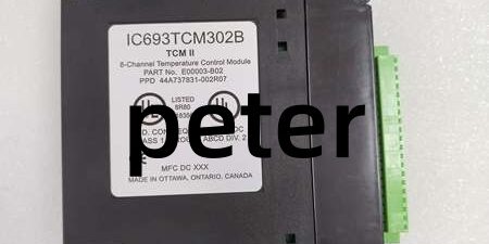
Product Core Brief
- Model:
- Brand: GE Fanuc / GE
- Series: Series 90-30 PLC
- Core Function: Provides 8 independent temperature control zones; accepts thermocouple inputs and drives time-proportioned outputs with onboard PID.
- Product Type: 8-Channel Temperature Control Module (TCM)
- Key Specs: Built-in cold junction compensation | Per-channel PID / On-Off control | 1500 VAC field-to-backplane isolation Note: OEM discontinued hardware; factory new stock scarce, surplus and refurbished units widely traded. Occupies one single-width Series 90-30 rack slot. Hot swapping is not supported.
Key Technical Specifications
- Channel Configuration: 8 independent zones (8 thermocouple inputs + 8 solid-state control outputs)
- Supported Thermocouple Types: J, K, T, E, R, S, B, N
- Resolution: 12-bit temperature measurement
- Control Modes: Per-channel On/Off or PID closed-loop regulation
- PWM Period Range: 0.1 s to 60 s configurable
- Maximum Thermocouple Lead Impedance: 30 Ω per channel
- Output Ratings: 100 mA maximum per channel; 18–30 VDC external field supply
- Off-State Leakage: ≤0.1 mA per output
- Backplane Power Draw: 150 mA @5 VDC
- Internal Protection: 2 A, 125 V subminiature field fuse
- Isolation: 1500 VAC 1-minute withstand, field circuits to logic backplane
- Operating Temperature: 0°C to 55°C horizontal cabinet mounting
- Storage Temperature: -40°C to 85°C
- Termination: Dual pluggable captive screw terminal connectors
- Diagnostics: Open thermocouple detection, reversed sensor detection, over/under temperature alarms, short-circuit monitoring
- Status LEDs: Power, Run, Fault, individual channel status indicators
Product Introduction
This unit executes standalone multi-zone thermal control for ovens, extruders and heat treatment equipment. Each channel reads thermocouple signals, applies cold junction compensation and runs PID algorithms locally without continuous CPU intervention.
Onboard control reduces backplane data traffic. Engineers tune PID gains, alarm thresholds and output behavior channel-by-channel within Logicmaster 90-30 programming software.
QA & Testing SOP (Transparency Building)
- Incoming Inspection: Verify part marking and hardware revision suffix. Inspect edge connector pins for deformation or corrosion; examine terminal connector housings for cracks.
- Live Testing: Mount into validated Series 90-30 rack, apply backplane power and external 24 VDC field supply. Inject simulated thermocouple signals and verify PID output cycling across all channels over a 24-hour continuous run.
- Electrical Testing: Use Fluke 115 to monitor backplane rail stability. Insulation resistance testing must exceed 10MΩ between field terminals and chassis protective ground.
- Firmware/Config Backup: Record module firmware revision. Photograph existing terminal wiring layout before disassembly.
- Final QC & Packaging: Place unit inside anti-static shielding. Attach dated QC test tag listing channel functional test results prior to shipment.
Installation Pitfalls & Guide (Engineer to Engineer)
❗ No Hot Swap Support: Series 90-30 backplane does not support live module insertion or removal. Power down the entire rack before extracting or installing the unit. ❗ Thermocouple Polarity Risk: Reversed thermocouple wiring triggers sensor fault alarms and invalid temperature readings. Always confirm polarity at both sensor and module terminals. ❗ Lead Resistance Limit: Thermocouple wiring with total impedance above 30 Ω degrades measurement accuracy. Use heavy-gauge thermocouple extension wire for long cable runs. ❗ ESD Dangers: Un-grounded handling can damage cold junction compensation circuitry. Static faults often appear as slow, drifting temperature readings after commissioning. ❗ External Power Dependency: Output drivers require a separate 18–30 VDC field supply. Backplane power alone cannot switch heater loads. Loss of field power disables all control outputs.
Replacement Guide:
- Pre-install: Execute lockout-tagout on rack power and external field supply; back up module configuration and photograph all wiring.
- Removal: Unplug both terminal connectors, unlatch module and slide straight out without twisting edge connectors.
- Install: Seat new unit fully into vacant rack slot, lock latches, reattach terminal blocks and replicate all wiring connections.
- Power-on Test: Restore power, download saved configuration, verify thermocouple readings and confirm PID output modulation operates without diagnostic faults.
FAQ (Frequently Asked Questions)
Q: Does this module support hot swapping? A: No. The Series 90-30 backplane lacks hot-swap bus logic. Live removal disrupts rack communications and risks permanent backplane damage. Full rack shutdown is mandatory.
Q: Can this hardware be used inside RX3i racks? A: No. It is designed exclusively for Series 90-30 chassis. Mechanical form factor and backplane signaling are incompatible with RX3i systems.
Q: What is the difference between IC693TCM302 and ? A: The -B suffix denotes updated hardware revision with improved cold junction compensation stability. Confirm revision matching when performing direct drop-in replacement to avoid minor calibration offsets.
Q: Does the module support RTD sensors? A: No. Inputs are dedicated thermocouple circuits. Select separate RTD modules if resistance temperature devices are required.
Q: Can PID parameters be adjusted while the system is running? A: Yes. Tuning values can be modified online via programming software. Always document active gains before making live adjustments to thermal zones.
Q: What happens if the internal field fuse blows? A: All control outputs disable. The fuse is field-replaceable; do not install a higher current rating as this removes short-circuit protection.
Q: Will saved configuration transfer directly to a replacement unit? A: Parameter sets import without modification. After replacement, verify cold junction readings and perform sensor calibration checks to ensure consistent measurement accuracy.




