Product Core Brief
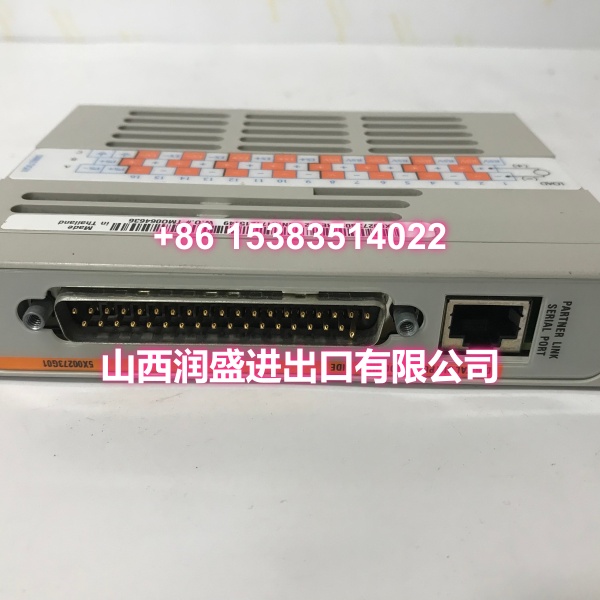
- Model: 5X00273G01
- Brand: EMERSON (Ovation / Westinghouse)
- Series: Ovation DCS
- Core Function: Digital Output (DO) module that converts controller logic outputs into discrete switching signals to drive field actuators such as relays, solenoid valves, motor starters, and indicator lights. Provides galvanic isolation between the controller and field devices to protect against voltage spikes and ground loops.
- Product Type: Digital Output Module / DO Card
- Key Specs: Digital Output | Ovation DCS Compatible | Galvanic Isolation | Hot-Swappable
- Condition: New Original / New Surplus
Key Technical Specifications
- Module Type: Digital Output (DO)
- Function: Converts controller output commands into discrete switching signals for field devices
- Compatibility: Ovation DCS; used in OCR161, OCR400, and OCR1100 controller I/O subsystems
- Output Type: Discrete digital switching (typically 24VDC or 125VDC, depending on configuration)
- Channel Configuration: Multiple independent digital output channels with per-channel or per-group isolation
- Isolation: Galvanic isolation between field circuits and controller backplane to prevent ground loops and voltage transients
- Power: Field power supplied via Ovation I/O backplane; no external module power required
- Operating Temperature: 0°C to 55°C, non-condensing (typical control room conditions)
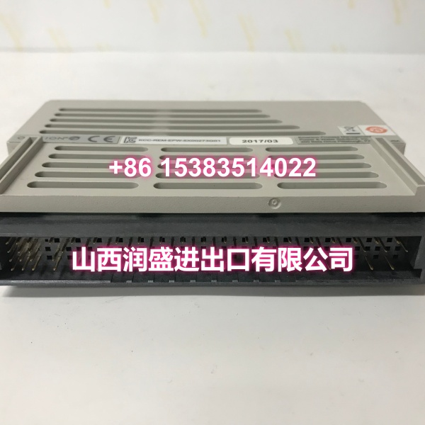
- Installation: Plug-in module for Ovation I/O base/chassis; hot-swappable
- Diagnostics: Front-panel LEDs and controller diagnostics support for channel-level fault detection
Product Introduction
The 5X00273G01 is a Digital Output (DO) module for the Emerson Ovation DCS, designed to convert controller logic outputs into discrete switching signals that drive field actuators such as relays, solenoid valves, motor starters, and indicator lights. This module is a core component in Ovation I/O subsystems, commonly deployed in power generation, water treatment, and petrochemical applications where reliable discrete control is critical.
Unlike controller-level interface cards (such as the IOIC cards 5X00226G01-G04) that manage communication between the CPU and I/O racks, the 5X00273G01 operates at the field device level. It receives output commands from the Ovation controller via the I/O backplane bus and switches the corresponding output channels on or off, directly controlling field equipment. Each output channel is galvanically isolated from the controller backplane, protecting the CPU and other modules from voltage spikes, ground loops, and field-side electrical disturbances.
The 5X00273G01 is part of Ovation’s modular I/O architecture. It plugs into a standard Ovation I/O base alongside other I/O modules (AI, AO, DI, TC, RTD, etc.) on the same branch. The module features front-panel status LEDs that provide immediate visual indication of channel state and health, enabling quick commissioning and troubleshooting without requiring an engineer station connection. As a hot-swappable design, the module can be replaced without powering down the I/O rack or interrupting adjacent channels—minimizing unplanned downtime during maintenance.
In typical applications, the 5X00273G01 is used for:
- Valve control: Opening/closing solenoid-operated isolation and control valves
- Motor control: Starting/stopping motor contactors and relay coils
- Alarm signaling: Driving audible/visual alarm devices and annunciator panels
- Interlock execution: Activating safety interlocks and permissive circuits
- Status indication: Controlling panel-mounted indicator lights and beacons
The module’s solid-state design with no mechanical wear points ensures long service life and low maintenance. It draws field power directly from the Ovation I/O backplane and features per-channel or per-group isolation to prevent a single channel fault from affecting the rest of the module or the controller.
QA & Testing SOP
Digital output modules are field-facing components—failure here can cause incorrect actuator operation or missed safety responses. Here’s our verification procedure:
- Visual & Anti-Counterfeit Inspection: We inspect the PCB for cold solder joints around the output driver ICs and backplane connectors, verify the OEM holographic label, and cross-check the silkscreen part number against the Ovation master parts list. Counterfeit DO modules in the surplus market may have degraded output drivers that fail under load or cause channel-to-channel crosstalk.
- Backplane & Connector Verification: The module is seated into a dedicated Ovation test rack. We inspect the backplane connector pins for bends or corrosion—bent pins on the field power side prevent the module from driving outputs; bent pins on the communication side prevent the controller from addressing the module.
- Controller Recognition Test: We install the module in a complete Ovation controller assembly and verify the controller recognizes the module without fault codes. We confirm the module appears in the Ovation I/O diagnostic screen with the correct module type and channel count.
- Channel-by-Channel Output Test: We write output commands from the Ovation engineer station to each channel individually and verify the corresponding front-panel LED illuminates. We then measure the output voltage at each terminal block to confirm the channel switches correctly under load. We test both ON and OFF states for every channel.
- Isolation & Leakage Test: We verify galvanic isolation between field circuits and the controller backplane using a megohmmeter. We also check for channel-to-channel leakage to ensure that activating one channel does not inadvertently affect adjacent channels.
- Anti-Static Packaging: Passed units are sealed in static-shielded bags with desiccant, then double-boxed for transit.
Installation Pitfalls & Guide
Digital output modules are field-facing and carry switching currents—proper installation is critical for reliable operation. Here’s what to watch for:
- ❗ Field Power Verification: The 5X00273G01 requires field power from the Ovation I/O backplane to drive outputs. Before installation, verify the I/O rack power supply is operational and the correct field voltage (typically 24VDC or 125VDC) is present at the backplane. Installing the module without field power will result in outputs that appear healthy (LEDs may light) but cannot drive field devices.
- ❗ Correct Slot Configuration: The module must be installed in a slot that has been configured in the Ovation I/O Builder for the correct module type. Installing a DO module in a slot configured for a different module type (AI, DI, etc.) will cause the controller to flag a configuration mismatch fault. Always verify the slot configuration in the I/O Builder before physical installation.
- ❗ Wiring Polarity: Digital output modules have polarity-sensitive field terminals. Reversing the positive and negative connections can damage the output drivers or prevent the module from switching correctly. Always verify wiring polarity against the terminal block diagram before energizing the circuit.
- ❗ Load Current Limits: Each output channel has a maximum current rating. Exceeding this rating can damage the output driver. For loads that exceed the module’s per-channel current capacity (such as large motor contactors), use an intermediate relay between the module output and the load. Never connect high-current loads directly to the module output terminals.
- ❗ Hot-Swap Procedure: While the module is hot-swappable, always follow the proper Ovation hot-swap procedure: set all points on the module to Out of Service (Scan Off) in the I/O Builder before removal, then restore to In Service (Scan On) after installation. This prevents unintended output transitions during the swap.
- ❗ Grounding & Shielding: Ensure the I/O rack is properly grounded per Ovation installation guidelines. Field wiring should use shielded cable with the shield grounded at the cabinet side only (field side floating) to prevent ground loops and EMI interference.
4-Step Replacement Guide:
- Pre-Install: In the Ovation I/O Builder, select the slot containing the faulty module. Right-click and select Service → Set all Points Out of Service (Scan Off). Apply the change. Verify all output channels are de-energized at the field devices.
- Removal: Open the blue locking lever on the front of the module. Pull the electronic module straight out of the base. If the module includes a personality module (terminal block adapter), remove it separately. Inspect the base connector for debris or damaged pins before installing the replacement.
- Install: Insert the personality module (if applicable) into the base first, then slide the new electronic module into the base until it seats fully. Close the blue locking lever to secure the module. Verify the module is seated in the correct slot per the I/O configuration.
- Power-on Test: In the I/O Builder, select the slot and choose Restore Points to Original Status (Scan On). Apply the change. Monitor the Ovation diagnostic screen for module recognition. Verify all front-panel LEDs indicate normal operation. Perform a channel-by-channel output test: write output commands from the engineer station and verify each channel switches correctly at the field device.
Technical FAQ
Q: What is the difference between 5X00273G01 and other Ovation DO modules? A: The 5X00273G01 is a specific revision of Ovation Digital Output module. Ovation offers multiple DO module variants with different channel counts, voltage ratings, and output types (solid-state vs. relay). The G01 revision is commonly used in legacy Ovation systems (3.5 and earlier) and remains supported on Ovation 4.0 as a legacy-compatible component. For exact channel count and voltage specifications, refer to your Ovation system documentation or the module nameplate.
Q: Can this module be used for safety-critical interlocks? A: The 5X00273G01 is a standard digital output module designed for general-purpose discrete control. For safety-critical interlocks (such as turbine trip circuits, boiler protection, or ESD systems), Ovation offers dedicated safety-rated modules with higher reliability ratings and SIL certification. Always consult your Ovation system documentation and safety requirements before using standard DO modules in safety applications.
Q: Why are my outputs not switching even though the module LEDs are lit? A: If the module LEDs indicate output activation but the field devices are not responding, the most common causes are: (1) field power is not present at the I/O backplane, (2) wiring polarity is reversed, (3) the load current exceeds the channel’s current rating, or (4) the output driver for that channel has failed. First, verify field power at the backplane terminals. Then check wiring polarity and load current. If power and wiring are correct, the output driver may be damaged and the module should be replaced.
Q: Is this module compatible with Ovation 4.0? A: The 5X00273G01 was originally designed for legacy Ovation systems (3.5 and earlier) and Westinghouse Ovation controllers. It remains supported on Ovation 4.0 as a legacy-compatible component for existing I/O racks. For brownfield replacements, it is a direct drop-in replacement. If you’re unsure, verify compatibility with your specific Ovation version and controller model in the system documentation.
Q: What is the warranty on surplus units? A: We provide a 12-month warranty from the date of delivery on both new original and new surplus stock. This covers manufacturing defects, DOA failures, and any output switching or integration issues discovered during commissioning. It does not cover damage from improper installation—such as reversed polarity, overcurrent damage, ESD damage from handling without proper grounding, or configuration mismatches.