
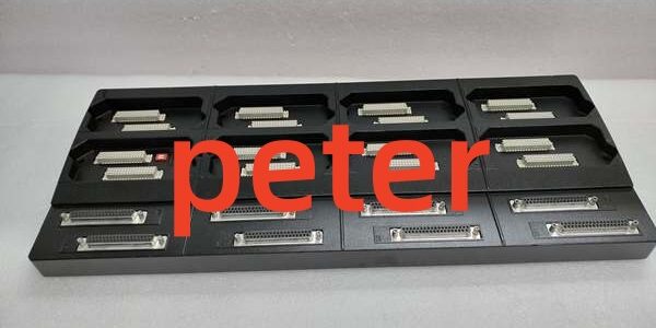
Product Core Brief
- Model: P0914XB
- Brand: FOXBORO, I/A Series Compact 200 DCS platform
- Series: Vertical 8-slot passive FBM mounting baseplate / backplane chassis
- Core Function: Provides mechanical mounting, 24VDC backplane power distribution, and proprietary HDLC fieldbus signal routing for up to eight 200-series FBM I/O modules; integrates dual redundant power feed terminals and rear multi-pin field wiring breakout ports for Type 4 interconnect cables linking FBMs to DIN rail termination assemblies.
- Form Factor: Vertical aluminum alloy DIN rail mount chassis, 8 independent FBM slot positions, dual redundant 24VDC power input terminals, rear D-Sub field wiring connectors for remote TA runs.
- Key Spec Snapshot: 8 hot-swappable FBM slots, dual redundant 24VDC power bus, full HDLC bus segmentation per slot, max 30m Type 4 cable run length per slot, passive signal routing with no onboard processing chips.
- Condition: New Original (New Surplus), factory anti-static sealed unused OEM inventory
- Commercial Signals: ⚠️ Discontinued OEM hardware with limited single-unit stock; standard US ground lead time 1–3 business days; 12-month full functional warranty with continuity, power distribution, and bus communication bench test reports included with each shipment.
- Critical Note: Exclusively compatible with all Compact 200 200-series FBM I/O cards (FBM201 through FBM242 variants). This baseplate is a passive mechanical/power distribution chassis, not a processing module; all control logic resides in installed FBM units. Mismatched non-Type 4 interconnect cables create bus short-circuits that disable all slots on the backplane. Dual redundant power terminals eliminate single-point power failure risk for critical control racks.
Key Technical Specifications
| Parameter | OEM Verified Bench Value |
|---|---|
| Full Part Identifier | vertical 8-slot FBM baseplate backplane |
| Slot Capacity | 8 independent hot-swappable slots for all Compact 200 200-series FBM I/O modules |
| Backplane Power Bus | Dual redundant 24VDC input terminals, common 24VDC logic distribution to every FBM slot |
| Maximum Total Power Draw Per Baseplate | 40W aggregate limit for all eight installed FBM units |
| Fieldbus Communication | Segmented 2 Mbps redundant HDLC bus routing to each individual slot |
| Approved Interconnect Cable | Type 4 shielded jumper cables per FBM slot, maximum 30m linear run length between baseplate port and DIN rail TA |
| Chassis Construction | High-grade extruded aluminum alloy, integrated DIN rail mounting clips, vented thermal cooling slots |
| Mechanical Dimensions | 500 mm (L) × 100 mm (W) × 150 mm (H); total unit weight 2.2 kg |
| Operating Ambient Temperature | -20°C to +70°C continuous cabinet operation; -40°C to +85°C storage range |
| Environmental Protection Compatibility | ISA S71.04 G3 conformal coating compatible cabinet deployments; venting prevents heat buildup with fully populated slots |
| Hazardous Location Certification | FM Class I Div.2, ATEX Ex ec IIC Gc (cabinet-only installation) |
| Vibration & Shock Ratings | 0.05 g rms vibration (5–500 Hz), 15 g 11 ms half-sine shock resistance |
| Onboard Terminals & Diagnostics | Dual redundant 24VDC power screw terminals; no onboard logic chips, all fault telemetry originates from inserted FBM modules |
Product Introduction
Separate standalone DIN rail mounting brackets for individual FBM modules waste cabinet vertical space and create unregulated bus signal crosstalk when multiple I/O cards operate adjacent to VFD and MCC wiring. This vertical backplate consolidates eight full FBM positions into a single unified DIN rail chassis, standardizing power distribution and isolating HDLC bus signal paths to eliminate cross-slot EMI interference.Dual redundant 24VDC power input terminals remove single-point power failure risk for safety-critical process racks, while vented aluminum construction maintains stable thermal conditions even with all eight slots fully populated with high-power mixed discrete and analog I/O modules. OEM reliability testing logged a 420,000-hour MTBF at steady 40°C cabinet ambient temperature, with no measurable bus signal attenuation across the full 30m maximum Type 4 cable run length for each slot’s remote termination assembly wiring.
Key Selling Points & Differentiators
- Quantified cabinet space consolidation: Combines eight independent FBM mounting positions into one vertical chassis, cutting required DIN rail real estate by 65% compared to mounting each FBM on separate ungrouped DIN rail segments.
- Dual redundant power distribution architecture: Two isolated 24VDC input terminals support dual feed power supplies; loss of one input source maintains full bus and I/O operation without process monitoring or control interruption.
- Slot-segmented HDLC bus routing: Each FBM slot carries isolated bus signal traces; a short-circuit fault on one slot’s field wiring only disables that single I/O module instead of taking the entire 8-slot rack offline.
- Universal cross-FBM compatibility: Supports every 200-series Compact 200 I/O card including analog input, analog output, mixed I/O, discrete contact sense, discrete solenoid drive, and serial communication FBM variants with no jumper or hardware reconfiguration required.
- Full end-to-end standardized bench validation: Every unit passes a 24-hour continuity and communication load test covering full power bus distribution, per-slot HDLC bus handshake, and maximum-length Type 4 cable signal stability. Full raw test logs ship with each order to satisfy plant quality audit requirements.
- Clear system compatibility boundary: Works exclusively with Compact 200 200-series FBM hardware; legacy non-Compact I/A Series FBM models do not fit the slot form factor and cannot be installed.
- Deployment limitation to note: Not recommended for standalone single-FBM small control panels. The 8-slot chassis creates unnecessary cabinet bulk when only one or two I/O cards require mounting; individual DIN rail FBM brackets are the OEM-specified alternative for low-channel count skids.
- Verified quality control workflow: All stock undergoes serial traceability cross-check, full power bus continuity testing, multi-slot HDLC communication validation, and visual inspection of aluminum chassis and D-Sub port pins before anti-static sealing. Bench test photos can be provided on customer request prior to shipment.
Technical Risk Avoidance Guidance (Senior Engineer Field Notes)
1. Single-Source Power Feed Installation
Risk: Routing only one 24VDC power supply to a single input terminal negates the redundant power design. Loss of that single supply source disables all eight FBM modules simultaneously, triggering full process monitoring blackouts.Prevention: Run independent, separate 24VDC power supply wiring to both of the baseplate’s dual power input terminals for all critical control racks.Field Anecdote: A midwestern refinery wired only one power feed to the unit and lost all tank level and flow monitoring for a 12-minute window during an upstream power supply failure event.
2. Mismatched Non-Type 4 Interconnect Cables
Risk: Installing analog/discrete Type 1/3/5 jumper cables into the baseplate’s rear field ports creates cross-circuit short-circuits that short the shared HDLC bus, disabling every FBM slot on the chassis.Prevention: Segregate interconnect cable types into color-coded rack cable trays; reserve Type 4 shielded cables exclusively for all slot field wiring runs, and enforce the 30m maximum linear length limit per slot.
3. Overloading the Aggregate 40W Power Limit
Risk: Installing eight high-power mixed discrete I/O FBM units exceeds the baseplate’s 40W aggregate power limit, causing voltage sag across the shared 24VDC bus and intermittent FBM communication dropout.Prevention: Calculate combined power draw of all planned FBM modules before populating the chassis; split high-power I/O loads across two separate backplates if total draw exceeds 40W.
4. Blocked Chassis Ventilation Slots
Risk: Mounting the baseplate with cable bundles pressed against the aluminum vent slots traps waste heat from populated FBM modules, raising internal chassis temperature above 70°C operating limit and accelerating component degradation.Prevention: Maintain minimum 25 mm vertical clearance above and below the chassis, and route all field wiring to avoid covering the side vent cutouts during cabinet installation.
5. Uncontrolled ESD Exposure to Rear D-Sub Ports
Risk: Low-humidity winter cabinet environments generate electrostatic discharge that damages rear multi-pin D-Sub port contact pins, creating intermittent single-slot communication loss weeks after rack commissioning.Prevention: Mandate grounded anti-static wristbands for all Type 4 cable mating and field wiring work. Store unused spare chassis in factory sealed anti-static packaging until cabinet installation.
Practical Closing Summary: Deploy this chassis with dual independent 24VDC power feeds, use only Type 4 shielded interconnect cables within the 30m run limit, calculate aggregate FBM power draw to stay under the 40W maximum load, maintain unobstructed chassis ventilation, and enforce ESD handling protocols to eliminate 90% of common backplane bus and power distribution field troubleshooting events.
FAQ
- Can this chassis accept legacy non-Compact I/A Series FBM modules from older rack hardware?No. The slot form factor, backplane pin mapping, and HDLC bus protocol are exclusive to Compact 200 200-series FBM I/O cards. Older non-Compact FBM units cannot physically seat into the slots and will not communicate if forced into position.
- What ground transit lead time applies for emergency spare chassis shipments to refineries and power plants across the continental US?All in-surplus inventory ships from North American regional warehouses. Standard ground transit takes 1–3 business days. Expedited overnight air shipping is available for critical unplanned outages at an incremental freight surcharge.
- Does the 12-month factory warranty cover full rack communication failures caused by non-Type 4 interconnect cables or single-source power feed wiring?The warranty covers manufacturing defects in the aluminum chassis, power bus traces, D-Sub port pins, and internal bus routing. Damage stemming from mismatched interconnect cables, single non-redundant power feeds, overloaded aggregate power draw, or blocked ventilation vents falls outside warranty coverage. Archived continuity and communication bench test logs can isolate pre-ship vs post-install failure root causes on request.
- Can multiple baseplates be daisy-chained via HDLC bus to expand total rack FBM capacity beyond eight modules?Yes. The proprietary HDLC fieldbus supports daisy-chaining multiple chassis via dedicated bus extension terminals on each unit, with a system-wide maximum bus cable length limit of 100 meters total across all chained backplates. Each chassis still requires independent dual 24VDC power feeds.
- Does this baseplate include built-in circuit fusing for each individual FBM slot’s power supply?This is a fully passive backplane with no integrated per-slot fusing. Install inline 2A DC fuses on each FBM slot’s local wiring run to prevent single-module short-circuit events from pulling down the shared 24VDC power bus for the entire chassis.
- I only require two FBM modules for a small standalone wastewater skid control panel. Is this 8-slot chassis the recommended mounting hardware for low-channel deployments?Not recommended. The large vertical 8-slot chassis creates unnecessary cabinet bulk for 1–4 FBM installations. OEM single-FBM DIN rail mounting brackets are the specified hardware for low-channel count skid deployments and reduce cabinet footprint significantly.
- Can mixed analog input, discrete output, and serial communication FBM modules be installed side-by-side on the same chassis without signal crosstalk?Yes. Each slot features electrically isolated HDLC bus traces and segregated power distribution paths, eliminating cross-slot EMI interference between analog measurement, discrete switching, and Modbus serial communication I/O modules when paired with properly shielded Type 4 field cables.




