
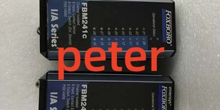
Product Core Brief
- Model: FBM241C, OEM factory part number P0914WM
- Brand: FOXBORO, I/A Series Compact 200 DCS hardware platform
- Series: Mixed channel-isolated discrete input / discrete output hybrid interface module
- Core Function: Combines eight 15–60VDC contact discrete inputs and eight externally powered discrete outputs in one DIN rail slot; reads limit switch, auxiliary relay and equipment status contacts, and drives solenoid valves, motor starters and indicator lights. Every channel carries independent galvanic isolation to contain field short-circuit faults to a single circuit.
- Form Factor: Hot-swappable compact DIN rail module with integrated aluminum heat sink; rear 37-pin D-Sub connector links to dedicated RH914WM passive compression-screw termination assembly via Type 4 shielded interconnect cable (30m maximum total run length).
- Key Spec Snapshot: 8 isolated DI + 8 isolated DO channels, 600VAC per-channel isolation, 2A DC / 5A AC per output channel, configurable 0/4/8/16/32ms input debounce, onboard ladder logic and user-programmable fail-safe output state.
- Condition: New Original (New Surplus), factory anti-static vacuum sealed unused OEM inventory
- Commercial Signals: ⚠️ Discontinued OEM hardware with limited matched module + RH914WM stock; standard US ground lead time 1–3 business days; 12-month full functional warranty with complete 24-hour load bench test reports provided with each shipment.
- Critical Note: Distinct from FBM241b (internal low-current output power) and FBM241d (low-resistance winding sensing); this hybrid unit requires external field excitation for all output loads. Only RH914WM termination assembly passes OEM impedance and isolation matching validation; generic third-party terminal blocks create unbalanced signal paths and risk permanent driver burnout. Redundant deployments allow two matching units sharing one RH914WM base for bumpless switchover.
Key Technical Specifications
| Parameter | OEM Verified Bench Value |
|---|---|
| Full Part Identifier | (P0914WM) mixed discrete input/output module |
| Channel Allocation | 8 galvanically isolated discrete input circuits, 8 galvanically isolated discrete output circuits |
| Input Signal Range | 15–60VDC dry contact sensing; open-circuit 24VDC ±15%, short-circuit nominal 2.5mA per channel |
| Output Supported External Load Voltages | 15–60VDC resistive/inductive DC loads, 120/240VAC relay/solenoid AC loads |
| Per-Channel Continuous Output Rating | 2A max DC, 5A max AC inductive loads; total simultaneous 8-channel limit 12A aggregate |
| Off-State Output Leakage Current | ≤0.1mA to eliminate false solenoid actuation |
| Input Debounce Filter Options | Software selectable: 0 ms, 4 ms, 8 ms, 16 ms, 32 ms per input channel |
| Channel Isolation Dielectric Rating | 600VAC 1-minute withstand between individual channels and backplane ground |
| Local Onboard Processing | Discrete ladder logic execution, momentary/sustained pulse output modes, configurable fail-safe fallback (de-energized / hold last state) |
| Backplane Fieldbus | Dual redundant 2 Mbps HDLC Compact 200 proprietary fieldbus |
| Module Logic Power Consumption | Max 5W, draws 24VDC exclusively from rack backplane; all field output loads require separate external excitation power |
| Valid Matching Termination Assembly | RH914WM flame-retardant polyamide compression screw TA |
| Approved Interconnect Cable | Type 4 shielded jumper cable, maximum total run length 30m between module and TA |
| Operating Ambient Temperature | -20°C to +70°C continuous cabinet operation; -40°C to +85°C storage range |
| PCB Environmental Protection | ISA S71.04 G3 conformal coating for corrosive refinery, chemical and wastewater cabinet atmospheres |
| Hazardous Location Certification | FM Class I Div.2, ATEX Ex ec IIC Gc (cabinet-only installation) |
| Mechanical Dimensions & Weight | H130 × W25 × D150 mm; unit weight ~185g |
| Front-Panel Diagnostics | Run/fault LED indicator, hardware watchdog timer, single-channel open/short circuit fault telemetry transmitted to host FCP controller |
Product Introduction
Separate dedicated discrete input and discrete output modules double rack slot usage and multiply field wiring labor for facilities running paired equipment status monitoring and valve/pump actuation loops. This hybrid unit consolidates 16 total discrete signal paths into one single DIN rail slot, reducing cabinet footprint and marshalling overhead for refining, power and water treatment DCS deployments.Every input and output channel features standalone galvanic isolation, so a shorted field cable or grounded relay coil only disables that individual circuit without taking the entire module offline. Onboard ladder logic offloads simple interlock and pulse timing workload from host FCP controllers to reduce HDLC bus latency, while user-selectable debounce filtering eliminates false status triggers from vibration-induced contact chatter on pump skid limit switches. OEM reliability testing logged a 310,000-hour MTBF at steady 40°C cabinet ambient temperature, with <16ms bumpless switchover when paired for redundant hot-swap maintenance.
Key Selling Points & Differentiators
- Quantified cabinet space reduction: Consolidates eight equipment status monitoring inputs and eight valve/relay control outputs into one slot, cutting required rack real estate by 50% compared to deploying standalone DI and DO modules side-by-side. Field wiring terminal count drops by 52% for identical discrete loop capacity.
- Independent per-channel fault containment: Isolation barriers restrict short-circuit damage to one single discrete circuit; group-isolated I/O hardware disables an entire bank of signals during a single field fault, creating unplanned blind monitoring zones that raise safety risk.
- Configurable signal conditioning onboard: Adjustable input debounce filtering eliminates false contact alarms without external RC filter hardware, lowering field maintenance labor hours and removing extra points of signal failure.
- Redundant hot-swap compatible architecture: Two matching units share one termination assembly for fault-tolerant critical interlock loops; technicians can remove and replace one unit while the secondary channel maintains uninterrupted pump and valve control.
- Full end-to-end standardized bench validation: Every complete set passes a 24-hour continuous load test covering contact status accuracy, output switching cycles, short-circuit protection and redundant switchover timing. Full raw test logs ship with each order to satisfy plant quality audit requirements.
- Clear host firmware compatibility boundary: All feature sets unlock fully on FCP280 controllers; FCP270 hosts require minimum V11.0 firmware revision to access debounce tuning, fail-safe output programming and ladder logic editing menus.
- Deployment limitation to note: Not recommended for safety instrumented system (SIS) interlock execution. This mixed I/O device lacks SIL certification; dedicated SIL-rated single-function discrete modules are required for SIS valve and contact monitoring loops per IEC 61508.
- Verified quality control workflow: All stock undergoes serial traceability cross-check, 500V megger insulation testing, power-on self-test handshake, and full discrete I/O simulation before anti-static sealing. Test photos or bench video can be provided on customer request prior to shipment.
Technical Risk Avoidance Guidance (Senior Engineer Field Notes)
1. Host Firmware Mismatch
Risk: FCP270 controllers running firmware older than V11.0 lock debounce filter and ladder logic configuration menus. Operators cannot suppress vibration-induced false contact alarms or program safe valve fallback states, forcing all fault logic to run on the host bus and increasing HDLC latency.Prevention: Pull controller firmware revision before ordering spare hardware; schedule firmware upgrades to V11.0 or newer if deploying this component.Field Anecdote: A midwestern wastewater facility deployed unupdated FCP270 hardware alongside the unit and received constant false tank high-level switch alarms for three weeks until a scheduled firmware patch window.
2. Mismatched Termination Assembly Hardware
Risk: Substituting non- TAs breaks calibrated discrete signal pin mapping. Contact status readbacks become erratic, and sustained short-circuit events can burn internal output driver semiconductors.Prevention: Standardize spare part labeling to separate for mixed discrete I/O from RH-series TAs built for analog or high-current standalone DO modules. Cross-reference the device part number before TA replacement.
3. Improper Compression Screw Torque on
Risk: Under-torqued field wiring creates variable contact resistance that generates flickering equipment status feedback and erratic valve cycling. Over-torquing cracks the polyamide TA housing and fractures internal printed-circuit signal traces.Prevention: Follow OEM specified torque value for all field wire terminals; install copper wire ferrules on all stranded field cables to stabilize contact pressure during cabinet temperature cycling.
4. Non-Type 4 Interconnect Cable Installation
Risk: Analog or discrete Type 1/3/5 jumper cables have misaligned D-Sub pinouts, creating cross-circuit short circuits that permanently damage the unit’s internal switching hardware.Prevention: Segregate interconnect cable types into color-coded rack trays; reserve Type 4 shielded cables exclusively for mixed discrete I/O module to runs. Maximum total cable run length capped at 30m per OEM specification.
5. Under-Calculated Rack 24VDC Power Budget
Risk: Undersized rack power supplies cannot maintain stable 24VDC backplane voltage during simultaneous full-channel output switching cycles. The device triggers intermittent fault telemetry and drops redundant channel synchronization.Prevention: Sum total power draw of all I/O modules on each baseplate, add a mandatory 20% overhead buffer before sizing rack power hardware. Four fully populated sets draw approximately 20W combined at peak switching load.
6. Unsuppressed Inductive Load Kickback
Risk: Unprotected solenoid and relay coils generate high reverse voltage spikes that degrade the unit’s solid-state output drivers over time, causing intermittent channel dropout and premature module failure.Prevention: Install freewheeling diodes (DC loads) or MOV snubbers (AC loads) directly across all inductive field load terminals on the wiring landings.
7. Uncontrolled ESD Exposure
Risk: Low-humidity winter cabinet environments generate electrostatic discharge that scratches gold-plated backplane edge connectors and degrades onboard switching semiconductors. Damage does not appear immediately, but manifests as random single-channel status drift weeks after commissioning.Prevention: Mandate grounded anti-static wristbands for all module insertion, cable mating and field wiring work. Store unused spare hardware in factory sealed anti-static packaging until rack installation.
Practical Closing Summary: Deploy this component paired exclusively with TAs and Type 4 interconnect cables, fit snubber protection for all inductive loads, confirm host controller firmware meets minimum revision standards, calculate rack power load with overhead buffer, and enforce ESD handling protocols to eliminate 90% of common mixed discrete I/O field troubleshooting events.
FAQ
- Can this component serve as a direct drop-in replacement for separate standalone FBM207 DI and FBM242 DO modules without full rack rewiring?No. While backplane physical compatibility exists, the pinout and channel addressing layout differ from single-function discrete TAs. Full workstation I/O reconfiguration and field terminal rewiring are required to swap from split DI/DO hardware to this mixed unit.
- What ground transit lead time applies for emergency spare shipments to refineries and power plants across the continental US?All in-surplus inventory ships from North American regional warehouses. Standard ground transit takes 1–3 business days. Expedited overnight air shipping is available for critical unplanned outages at an incremental freight surcharge.
- Does the 12-month factory warranty cover channel switching failures or contact readback errors caused by unapproved third-party termination assemblies?The warranty covers manufacturing defects in switching circuits, isolation barriers, HDLC bus transceivers and terminal contact hardware. Damage stemming from mismatched TAs, improper wire torque, out-of-spec interconnect cables or unsuppressed inductive load kickback falls outside warranty coverage. Archived 24-hour bench test logs can isolate pre-ship vs post-install failure root causes on request.
- What maximum total linear length of Type 4 shielded jumper cable can run between the unit and without measurable signal attenuation and false contact chatter?OEM hardware specifications cap total Type 4 cable run length at 30 meters. Longer cable runs introduce excess loop resistance and industrial VFD-generated EMI noise that triggers unstable discrete status feedback and random output dropout.
- Does include built-in channel fusing for short-circuit field wiring protection? is a fully passive termination assembly with no integrated per-channel fuses. Install inline field fuses sized for 2A DC / 5A AC loads at each TA wire landing to prevent sustained short-circuit current from damaging the unit’s internal output drivers.
- I need to deploy redundant pump interlock monitoring paired with modulating solenoid valve control loops for SIS safety interlock racks. Is this mixed discrete I/O hardware acceptable for SIS final element wiring?Not recommended. This component carries no SIL safety certification, and mixed input/output channel architecture does not meet independent segregation requirements outlined in IEC 61508 for safety instrumented systems. Deploy dedicated SIL-rated single-function discrete modules for all SIS contact and valve control circuits.
- I run a batch chemical plant with high-vibration mixer skids that create constant contact bounce on limit switches. Can the onboard debounce filtering eliminate false fault alarms without external hardware?Yes. Software-selectable 4–32ms debounce timing runs locally on the unit’s processing logic, removing high-frequency chatter from contact status signals before data transmits to the host controller. No external RC filter networks need to be wired at the terminals.




