
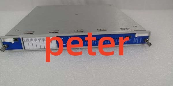
Product Core Brief
- Model: 3500/33 (base 16-channel relay module; front card PWA variants 133292-01 / 149986-01, matched rear terminal base PN 149992-01)
- Brand: Bently Nevada (Baker Hughes)
- Series: 3500 Machinery Protection TSI Rack System
- Order Suffix Breakdown:
- XX = Channel configuration (01 = standard 16 SPDT output layout)
- XX = Conformal coating grade (00 = standard industrial uncoated; 01 = coated offshore rated)
- Core Function: Full-width high-density relay module that executes custom AND/OR/2oo2/2oo3 voting logic to drive hardwired alarm panels, plant ESD shutdown circuits, and rack fault indication contacts from all rack monitor channels
- Product Type: Single full-height hot-swappable split front/rear base relay output module
- Key Specs: 16 independent epoxy-sealed SPDT relays | 5.8 W typical power draw | 1500 VAC channel-to-logic isolationBaker Hughes DAM
- Condition: New Original factory sealed with OEM lead time; fully bench-tested refurbished surplus ships within 3 working days
Key Technical Specifications
- Relay Channel Count: 16 fully isolated SPDT outputs, grouped into four sets of four channels for bulk energize/de-energize DIP selectionBaker Hughes DAM
- Resistive Contact Ratings: 5 A @ 250 VAC; 5 A @ 30 VDC; built-in 250 Vrms arc suppression diodes per relay coil
- Logic Programming Capability: Each channel independently maps Alert, Danger, Not-OK, and measured variable status from any monitor card across the rack backplane; software-selectable latching with remote hardwire or software reset
- Power Consumption: 5.8 W continuous load supplied via rack 24 VDC backplane bus
- Galvanic Isolation Rating: 1500 VAC separation barrier between field relay contact wiring and internal rack logic circuits
- Operating Ambient Range: −30 °C to +65 °C standard cabinet; coated suffix variants extend service range to −40 °C to +85 °C offshore platforms
- Relay Mechanical Lifespan: Minimum 100,000 full actuation cycles under full rated resistive load
- Physical Dimensions: 241.3 mm H × 24.4 mm W × 241.8 mm D; front card weight 0.7 kg, rear terminal base 0.4 kgBaker Hughes DAM
- Compliance Standards: API 670, CE EMC, UL Class I Div 2, ATEX Zone 2 Ex nC IIC T4
- Front Panel Status Indicators: OK (module health), TX/RX (backplane communication), dedicated CH ALARM LED per relay channel to flag active trip statesBaker Hughes DAM
- Critical Safety Feature: All relay trip logic operates fully independent of rack communication gateways; LAN outages do not break hardwired ESD shutdown contact operation
Product Introduction
Large steam and gas turbine protection racks require dozens of discrete hardwired contacts to feed local alarm annunciators and safety shutdown systems, and this unit consolidates 16 relay outputs into one rack slot to eliminate stacking multiple low-density 4-channel 3500/32M relay cards. It continuously polls vibration, temperature, speed, and analog PV monitor modules over the passive backplane to execute user-programmable safety voting without external PLC logic intervention.Its modular rear terminal base design lets maintenance technicians rework field wiring, add external surge suppression hardware, or repair damaged screw terminals without extracting the front relay card during planned equipment outages. This component contains zero transducer signal conditioning circuitry; it only processes digital fault/status flags generated by measurement cards installed elsewhere in the rack. Not recommended for small auxiliary pump racks requiring fewer than six discrete alarm/shutdown contacts, as lower-density relay hardware delivers better cost efficiency for low I/O layouts.
Key Selling Points & Differentiators
- 16-channel high-density architecture cuts required rack slot count by 75% compared to 4-channel relay modules, reducing total cabinet footprint for full turbomachinery TSI systems.
- Native support for 2oo3 TMR redundant voting meets API 670 single-point failure elimination rules for critical compressor and turbine safety interlock design.
- Epoxy-sealed relay coils and contacts resist dust, humidity, and minor cabinet condensation, extending usable service life in unconditioned refinery and offshore control enclosures.
- Per-channel software latching logic maintains fault indication after transient machinery trips until manual or software reset, simplifying post-fault root-cause diagnostic workflows.
- Refurbished surplus units carry a 12-month functional warranty covering relay driver circuits, backplane communication, and contact integrity; factory-new OEM assemblies ship with a full 36-month manufacturer performance warranty.
- Fail-safe de-energized relay configuration aligns with standard power generation safety design practices, automatically triggering shutdown contacts if rack backplane power is lost.
Quality Transparency SOP
- Incoming Verification: Cross-reference serial numbers against OEM M-series production archives to filter counterfeit assemblies. Complete visual audit of PCB relay driver traces, rear base screw terminals, front panel channel status LEDs, and rack edge gold pins; timestamp photos of terminal corrosion, burned contact traces, or cracked PCB substrates.
- Live Bench Test: Mount the front card and matched rear base into a calibrated full-size test rack powered by a Fluke 115 24VDC supply. Run continuous 24-hour load test with simulated Alert/Danger fault signals cycling all 16 relay channels to validate stable power draw and consistent backplane polling to the Slot1 TDI module.
- Electrical Tests: 500 V megohmmeter insulation test confirms resistance >10 MΩ between all relay contact terminals and rack protective ground; verify each relay’s arc suppression and overcurrent protection trigger thresholds match OEM factory limits.
- Firmware & Layout Backup: Flash the latest OEM M-series compatible firmware revision, log exact version numbers, and archive a blank 16-channel relay voting configuration file to offline storage. Record baseline LED behavior during 2oo3 safety voting simulation for post-replacement fault comparison.
- Final QC & Packaging: Cycle every relay channel 1,000 times to validate chatter-free contact closure under full rated load. Separate front card and rear base into anti-static foam inserts, attach serialized QC Passed tag with timestamped actuation test data, and seal inside rigid shock-resistant cardboard crates. Bench test logs and relay cycle reports are available to buyers on formal written request.
Technical Risk Avoidance Section
❗ Firmware Rev Mismatch Risk: Mismatched rack-wide M-series firmware revisions trigger permanent TX/RX communication faults and disable all relay voting logic. Export the full rack firmware stack before swapping the module; never deploy mixed legacy/M-series firmware sets across rack slots. Field anecdote: A combined-cycle power plant installed mismatched firmware revisions and lost all high-pressure compressor shutdown interlocks for 14 hours during startup commissioning.❗ Rear Terminal Base Mismatch Risk: Pairing the front card with any I/O base other than 149992-01 breaks 16-channel relay wiring pinouts and removes built-in contact surge suppression, creating inductive kickback damage to on-board relay driver ICs.❗ Inductive Load Without External Suppression Risk: Driving motor contactors, solenoid valves, or large pilot relays without external flyback diodes causes severe contact arcing, accelerating relay wear and creating intermittent trip contact failures mid-operation.❗ ESD Damage Risk: Ungrounded field tools touching exposed rear base terminal pins discharge static and destroy delicate relay driver circuits; OEM PCB repair labor costs exceed $1,600 for production M-series hardware. Prevention: Mandate grounded ESD wrist straps for all rack module insertion and removal work while the chassis is energized.❗ Missing Relay Voting Logic Backup Risk: Failing to export validated AND/OR/TMR voting schemes prior to replacement resets all shutdown and annunciation logic to blank factory defaults, removing critical turbomachinery fail-safe protection interlock coverage.
Quick summary: Pair only with OEM dedicated rear terminal base, unify rack firmware versions, add external flyback diodes for inductive loads, and maintain stored voting configuration backups to eliminate nearly all common relay module field failure modes.
FAQ
Q: Does this unit support live hot-swap operation with the rack energized?A: Yes, the front relay card is rated for hot-swap without full rack power loss. All active relay contact states hold their last valid position during removal and replacement, so machinery ESD shutdown interlocks do not drop out mid-service. The rear terminal base cannot be removed while energized.
Q: Can this assembly replace multiple 4-channel 3500/32M relay modules to reduce rack slot usage?A: Yes, one unit delivers four times the relay output count of a single 3500/32M card, drastically cutting slot consumption for large turbine and compressor protection racks. All identical voting, latching, and fail-safe state logic functions are fully supported.
Q: What warranty coverage applies to refurbished surplus inventory of this relay module?A: Refurbished assemblies carry a 12-month functional warranty covering relay driver circuits, backplane communication, and relay contact integrity. Cosmetic surface scuffs and minor terminal screw wear are excluded from claim eligibility. Factory-new OEM units ship with a full 36-month manufacturer warranty.
Q: Will rack power cycling erase stored relay voting logic, latching settings, and energize/de-energize channel configurations?A: No. All voting rules, relay state selections, and latching parameters write to non-volatile onboard flash memory; power loss or full rack shutdown does not clear saved relay configuration data.
Q: Can proximity probes, Velomitors, or RTD temperature sensors be wired directly to this module’s terminals for measurement?A: No. This hardware only accepts digital fault/status signals from other rack monitor cards and drives discrete relay contacts; it contains no analog signal conditioning circuitry for any field transducer type.
Q: I operate an auxiliary cooling pump rack that only requires four discrete alarm contacts. Is it acceptable to leave the remaining 12 relay channels unused?A: Yes. Unconfigured unused channels draw no extra backplane power and create no cross-channel interference. Install blank terminal jumpers on empty channel screw terminals to block dust buildup inside the rear base and reduce long-term insulation degradation.
Q: Does this module independently store transient machinery vibration or temperature fault waveform snapshots on its PCB?A: No. All timestamped transient fault waveform capture and local flash storage functionality is managed exclusively by the rack’s Slot1 TDI master communication module; this component only executes digital voting logic and drives hardwired relay outputs.




