Component Snapshot At-a-Glance
- Model: 4211
- Alt. P/N: No direct drop-in replacement; 4210 is copper-based short-distance variant, incompatible for long fiber field runs
- Product Series: Triconex Tricon V9/V10 SIL3 RXM Remote Expansion Communication family
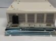
- Hardware Type: Rack-mounted triple-modular redundant fiber-based Tribus bridge PCB
- Key Feature: Dual SC fiber ports per card with independent isolated TMR signal paths for 2oo3 hardware voting
- Primary Field Use: Creates fiber-based communication trunk between main SIS chassis and geographically separated field remote I/O expansion racks.
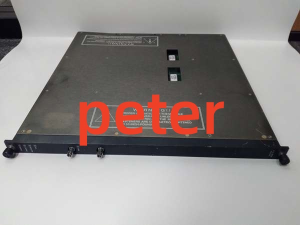
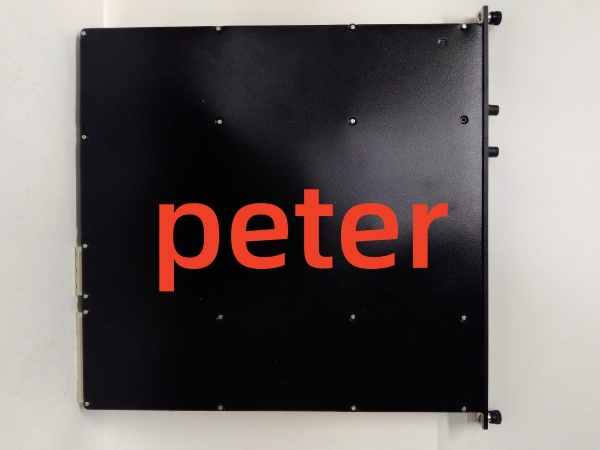
TRICONEX 4211
Hard-Numbers: Technical Specifications
- Protocol Support: Proprietary Tricon Tribus 25Mbps serial bus protocol
- Port Count: 2 SC-type fiber transceivers per individual 4211 module
- Max Fiber Distance: 1km multi-mode, 3km single-mode optical cabling
- Backplane Supply Rail: 6.5VDC from chassis PSU; typical power draw = 18W per card
- Isolation Rating: 2000VDC galvanic isolation between fiber front-end and backplane logic circuits
- Operating Temperature: 0°C ~ +60°C continuous rated; -40°C ~ +85°C non-operational storage range
- Fault Contact Output: Form-C dry contact rated 24VDC/1A for remote DCS fault annunciation
- Certification: IEC61508 SIL3, UL Class I Div 2, ATEX Zone 2 hazardous location certification
The Real-World Problem It Solves
Copper-based 4210 communication cards hit resistance limits past 150m field cabling, triggering random remote rack I/O dropout during large VFD motor startup transients. Mixed revision communication hardware breaks TMR inter-card sync and generates constant degrade flags inside TriStation diagnostic logs.
Where you’ll typically find it:
- Refinery FCC field hazardous-area remote I/O racks positioned hundreds of meters away from central control room SIS mainframe
- Coal-fired power boiler BMS outdoor cabinets tied to furnace flame detection and fuel shutoff safety I/O
- Onshore natural gas compressor HIPPS field racks monitoring pipeline high-pressure shutdown instrumentation
Fiber isolation eliminates ground-loop noise across long field cable runs and removes distance restrictions for distributed SIS remote rack deployment.
Hardware Architecture & Under-the-Hood Logic
No shared master microcontroller across internal TMR legs; three fully isolated transceiver sub-circuits process incoming Tribus data independently before hardware majority voting stage.
- Backplane Tribus bus data enters three segregated copper receiver circuits on card’s rear edge connector.
- Each isolated electrical signal converts to modulated optical transmission via dedicated onboard fiber transceiver hardware.
- Outbound light pulses route to front-panel SC fiber jacks for transmission across field optical cable to paired remote rack 4211 set.
- Incoming optical signals from opposite rack convert back to electrical data before three-way hardware comparison voting.
- Outlier data from a single faulty transceiver leg gets discarded automatically without interrupting valid bus communication flow.
- Onboard surface-mount thermistor reduces transceiver drive power above 63°C core temperature to slow optical component wear inside sealed warm cabinets.
TRICONEX 4211
Field Service Pitfalls: What Rookies Get Wrong
Mixing Different Firmware Builds Across Triplet 4211 SetNew maintenance staff installs one updated-revision 4211 alongside two older-version cards; inter-TMR timing drifts apart and causes intermittent brief remote rack comm blips during ambient temperature swings.
- Field Rule: All three 4211 cards in one remote chassis triplet must load identical TriStation firmware build before hot insertion into powered backplane.
Improper Fiber Bend Radius Exceeded During Cabinet Wiring RoutingTechnician crimps fiber cabling tight against cabinet frame creating sharp bends under minimum specified radius; rising optical attenuation triggers sporadic single-leg FAULT LED flicker.
- Quick Fix: Maintain minimum 30mm bend radius on all field fiber; secure runs with loose plastic cable ties only, avoid rigid metal clamps.
Running Instrument Copper alongside High-Voltage Motor Cable Trays Near Fiber TerminationField installers route unshielded auxiliary wiring within 20cm of 480V power cables; induced EMI creeps into card’s backplane edge pins and corrupts low-level Tribus reference signals.
- Field Rule: Separate all control wiring minimum 30cm from high-current power conduit; add ferrite bead clamp on backplane wiring entry point for high EMI compressor buildings.
Commercial Availability & Pricing Note
Please note: The listed price is for reference only and is not binding. Final pricing and terms are subject to negotiation based on current market conditions and availability.