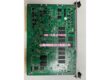
Product Core Brief
- Model:
- Brand: GE Fanuc / GE
- Series: Series 90-30 PLC
- Core Function: Delivers regulated multi-rail power to Series 90-30 backplanes; universal AC/DC wide-range input with integrated RS485 diagnostic communication.
- Product Type: Standard Capacity Universal Input Power Supply Module
- Key Specs: 30W total output | 85–264VAC / 100–300VDC input | Onboard RS485 diagnostic port Note: Discontinued legacy hardware; factory new stock scarce, surplus and refurbished units widely traded. Must occupy Slot 0 (far-left dedicated power slot). Hot swapping is not supported.
Key Technical Specifications
- Nominal Input: 120/240 VAC or 125 VDC
- Operating Input Range: 85–264 VAC (47–63 Hz); 100–300 VDC
- Total Rated Output Power: 30 W combined across all rails
- Output Rail Limits: +5 VDC (15 W maximum for backplane logic) +24 VDC Relay Power (15 W maximum) Isolated +24 VDC (20 W maximum)
- Minimum Hold-Up Time: 20 ms at full rated load
- Isolation Rating: 1500 VAC input-to-backplane isolation, 1-minute withstand
- Integrated Interface: RS485 serial port for power supply diagnostic monitoring
- Protections: Overvoltage, overcurrent, auto-recovering short-circuit shutdown
- Status Indicators: PWR, OK, RUN, BATT LED indicators
- Operating Temperature: 0°C to 55°C horizontal cabinet mounting
- Storage Temperature: -40°C to 85°C
- Form Factor: Single-width Series 90-30 slot
- Compatible Chassis: IC693CHS391, IC693CHS392, IC693CHS397, IC693CHS398
- Terminal Wire Range: 14 AWG to 22 AWG copper conductors
Product Introduction
This unit supplies multi-domain regulated power for Series 90-30 racks accepting mains AC or high-voltage DC plant power. It delivers logic power to the backplane plus separate 24V supplies for relay outputs and discrete field I/O modules.
Distinct from standard power supply variants, it includes an RS485 port to transmit operational status data. This feature enables remote monitoring of supply health, making it preferred for unmanned plant and remote machine retrofit projects.
QA & Testing SOP (Transparency Building)
- Incoming Inspection: Verify part marking and hardware revision suffix. Inspect edge connector pins for bending or corrosion; check terminal block housing for cracks.
- Live Testing: Mount to validated Series 90-30 backplane, apply nominal AC input. Load all output rails and monitor voltage stability through a continuous 24-hour run cycle; validate RS485 diagnostic communication.
- Electrical Testing: Use Fluke 115 to track rail regulation. Insulation resistance testing must exceed 10MΩ between input terminals and chassis protective ground.
- Documentation Check: Record hardware revision. Photograph input wiring layout before disassembly.
- Final QC & Packaging: Place unit inside anti-static shielding. Attach dated QC test tag listing steady-state voltage readings prior to shipment.
Installation Pitfalls & Guide (Engineer to Engineer)
❗ No Hot Swap Support: Series 90-30 backplanes lack hot-swap bus logic. Live removal crashes all rack modules and risks permanent backplane trace damage. Full rack power shutdown mandatory. ❗ Slot Placement Mandate: Install only in the far-left dedicated power slot (Slot 0). Insertion into regular I/O slots prevents backplane power distribution and will not operate. ❗ Model Mix-Up Risk: This standard capacity model cannot be treated as a direct drop-in for IC693PWR330. While input range matches, power allocation characteristics differ; recheck rack load budget before substitution. ❗ Bus Termination: If utilizing the diagnostic serial port, apply proper 120Ω termination at bus endpoints to avoid intermittent communication errors. ❗ ESD Dangers: Exposed backplane connector circuits are static-sensitive. Un-grounded handling can create drifting output regulation that appears after commissioning. ❗ Power Budget Miscalculation: Sum total power draw of all installed modules. Overloading the 30W total rating creates voltage sag, random CPU faults and intermittent module dropouts.
Replacement Guide:
- Pre-install: Activate lockout-tagout on rack input power; document all input wiring and bus connections.
- Removal: Disconnect AC/DC input terminals and serial wiring, unlatch module and slide straight out without twisting edge connectors.
- Install: Seat new unit fully into Slot 0, lock latches, terminate input wiring and re-establish bus connections.
- Power-on Test: Restore input power, confirm all status LEDs operate normally; power up CPU and verify all I/O modules are recognized by programming software.
FAQ (Frequently Asked Questions)
Q: Does this unit support hot swapping? A: No. The Series 90-30 backplane architecture does not support live power supply removal. Full rack power shutdown is required for replacement.
Q: What is the key difference between and IC693PWR330? A: Both share universal AC/DC input and 30W total output. includes an onboard diagnostic port; IC693PWR330 does not have serial diagnostics and offers revised power rail allocation flexibility. They are mechanically compatible but validate rack load and monitoring requirements before swapping.
Q: Can this power supply be used inside RX3i racks? A: No. Form factor, pinout and signaling are exclusive to Series 90-30 chassis. It cannot operate within PACSystem RX3i hardware.
Q: Can multiple power supplies run in parallel for redundancy? A: Load sharing and redundant parallel operation are not supported. Each rack requires one dedicated power supply. Deploy separate racks for fault-tolerant layouts.
Q: What data can be accessed via the diagnostic port? A: The serial interface provides power supply operating status, fault flags and runtime metrics for external monitoring systems. It is separate from the main PLC CPU communication bus.
Q: Can I use this unit on Series 90-30 remote expansion racks? A: Yes, it is compatible for expansion baseplates, provided the rack is configured to accept this universal input power supply. Confirm rack power budget before loading I/O modules.
Q: Will a replacement unit work without configuration changes? A: No PLC software configuration is required for basic power operation. If utilizing diagnostics, re-establish serial bus parameters after installation. Verify all rail voltages and monitor for intermittent fault codes caused by overloaded backplane loads.