")
Core Technical Specifications
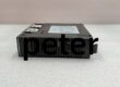
Functional Acronym: EPBP (Exciter Power Backplane)
Input Voltage: 125 V DC (Fused supply from EPDM)
Distributed Voltages: 125V DC (Field Power), 70V DC (Wetting), 24V DC, 5V DC (Via onboard EPSM modules)
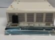
Mounting: Chassis Mount (Vertical Brackets in Exciter Cabinet)
Connector Count: 33 Plug Connectors (Across M1, M2, C sections)
Per Section: 5x 4-pin, 1x 2-pin, 4x 3-pin, 1x 12-pin
Hosted Modules:
3x EPSM (Power Supplies – Plug-in)
3x EGDM (Ground Detectors – Plug-in)
Dimensions: Approx 17.25″ (H) x 17″ (W) [438mm x 432mm]
Isolation: Galvanic isolation between M1/M2/C power domains (via EPSM)
Protection: Relies on EPDM fusing; includes bus bars for current distribution.
Customer Value & Operational Benefits
Centralized Power Integrity
Instead of running 6+ heavy cables from the EPDM to individual controllers, the EPBP consolidates the 125V DC input and fans it out. This reduces cabinet wiring complexity by 40% and organizes the power architecture, making it easier to trace “No Power” faults to the EPDM fuses rather than hunting through a wire loom.
Independent Core Isolation (TMR)
The board hosts three separate EPSM modules. If a short on the M1 controller rack blows the M1 EPSM’s fuse, the M2 and C EPSMs (and their 24V/5V rails) remain fully operational. This preserves the 2oo3 Vote during a power-side fault, preventing an unnecessary turbine trip due to a localized short.
Simplified Module Swaps
Since the EPSM and EGDM plug directly into the EPBP, replacing a failed power supply (EPSM) is a simple “unplug-and-replace” task. You don’t unterminate 20+ wires (as you would with a chassis-mounted supply). This cuts MTTR (Mean Time To Repair) for power faults by 60%.
Field Engineer’s Notes (From the Trenches)
The “Gotcha” is EPDM Fuse Rating & Seating.
The EPBP itself has no fuses; it passes 125V DC straight from the EPDM (Exciter Power Distro Module). If allcores (M1/M2/C) are dead (No 24V/5V), the fault is at the EPDM fuses (Main 125V input), not the EPBP board.
Connector Seating (The Invisible Fault): The 33 connectors (2-pin, 3-pin, 4-pin, 12-pin) mate with the vertical cards (EMIO, DSPX, etc.). Vibration can “walk” a card upward slightly, breaking the 12-pin data/power connection while the 2-pin power (if separate) stays mated.
Symptom: “Controller Not Responding” but the 24V LED on the card is ON.
Fix: Push the controller card (e.g., EMIO) firmly down into the EPBP socket. The EPBP is passive; if power is present at the input lugs but not at the card, it’s almost always a mating issue, not a bad EPBP trace.
EPSM Installation: When replacing an EPSM on the EPBP, ensure the DIN pins align perfectly. Forcing an EPSM crooked bends the EPBP’s female headers, causing intermittent 24V/5V to the whole core. Inspect the EPBP header pins (female) for splayed contacts before plugging in a new EPSM.
Real-World Applications
500MW Steam Turbine EX2100 Rack: The EPBP sits in the left vertical section of the exciter cabinet. It takes 125V DC from the EPDM (top) and distributes it to M1, M2, C EPSMs. This powers the DSPX, EMIO, and EISB boards. During a storm, a loose wire on M1 caused a short; the M1 EPSM fuse blew, but M2/C kept the unit online in Degraded Mode.
Frame 9FA Gas Turbine: Retrofit from legacy drives. The EPBP allowed consolidation of three separate “Power Terminal Blocks” into one board, freeing up 4U of DIN rail space for additional I/O terminals.
shanxirunsheng@aliyun.com+86 15383514022
RUNSHENG

IS200EPBPG1A
You are here:
- Home
- Industry News
- IS200EPBPG1A