Quick Sizing & Sourcing Snapshot
- Manufacturer: GE (General Electric)
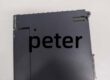
- Part Number: IS220PDIOH1A
- System Platform: Mark VIe (Speedtronic)
- Hardware Type: Combined Discrete Input/Output Pack (PDIO)
- Architectural Role: Consolidates 24 discrete inputs and 12 relay drivers into a single Ethernet-enabled I/O node, replacing separate PDIA and PDOA packs to interface with TDBS (Simplex) or TDBT (TMR) terminal boards.
- Key Specifications: 24 DI (Optically Isolated, 5-125V DC), 12 DO (Form-C Drivers), Dual 10/100M Ethernet, 28V DC Power Input.
System Architecture & Operational Principle
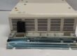
The is a distributed I/O pack operating at Level 1/2 of the Mark VIe architecture. It eliminates the need for separate input (PDIA) and output (PDOA) packs by integrating both functions into one housing, significantly reducing cabinet footprint.
Physically, it mounts either on a 35mm DIN rail or directly onto a terminal board (TDBS for Simplex, TDBT for TMR) via a DC-62 (37-pin) connector. Upstream, it connects to the Mark VIe controller (UCVE/UCVGH) over dual redundant IONet (RJ45 Ethernet) ports, supporting auto-negotiation and deterministic data exchange. Downstream, it handles field signals: the 24 inputs are optically isolated (1500V) and accept dry or wet contacts (5-125V DC) with a fixed 4ms hardware debounce filter to reject contact bounce and EMI. The 12 outputs are low-side switches (sinks) designed to drive the coil circuits of external interposing relays (e.g., SRLY on TDBS) or directly drive small solenoids. An onboard processor scans I/O locally, reducing controller load, and reports status via front-panel LEDs (Status, Boot, Fault, Net A/B, Active).
Core Technical Specifications
- Input Channels: 24 (Dry/Wet Contact Sensing, Optically Isolated)
- Input Voltage Range: 5 V DC to 125 V DC (Configurable via Terminal Board)
- Input Filter: Fixed 4 ms Hardware Debounce (Non-configurable in basic modes)
- Output Channels: 12 (Form-C Relay Drivers / Low-Side Switches)
- Output Capability: Sinking ~1A @ 28V DC (Drives external relay coils)
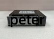
- Communication: 2x 10/100Base-TX (RJ45), Auto-MDIX, Redundant IONet
- Field Interface: 1x DC-62 (37-pin D-sub) to TDBS (Simplex) or TDBT (TMR)
- Power Input: 27.4 – 28.0 V DC (3-pin Micro-Fit, Soft-Start capable)
- Isolation: 1500 Vrms (Field Inputs to Logic/Network), 2500 Vrms (Relay Coil to Contacts on TB)
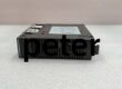
- Diagnostics: Status, Boot, Fault, Active, Net A, Net B LEDs (Faceplate)
- Mounting: DIN Rail (TS-35) or Direct-to-Board (TDBS/TDBT)
- Environmental: 0°C to +60°C (Operational), Conformal Coated
Customer Value & Operational Benefits
Cabinet Density & Cost Reduction
The PDIO concept merges 24 DI and 12 DO into one unit. This cuts I/O slot count (or DIN rail space) by roughly 50% compared to deploying a PDIA + PDOA pair. In skid-mounted controls or retrofits with tight panel real estate, this avoids upsizing enclosures, saving on fabrication costs and cable tray congestion.
Deterministic Local Processing
The onboard processor handles the 4ms hardware debounce and I/O scanning locally. It only reports state changes (“Contact Closed”) to the controller, preventing EMI spikes from VFDs or contactors from triggering false inputs or flooding the IONet bandwidth. This improves signal integrity for critical loops like lube oil pump status or ESD pushbutton monitoring.
Simplified Spares Strategy
Since one PDIO replaces two spare types, your warehouse only stocks the . Whether a balance-of-plant skid loses an input channel or a cooling fan output, the same module works for both. This eliminates “wrong spare” downtime scenarios and reduces inventory carrying costs.
Field Engineer’s Notes (From the Trenches)
The persistent “Gotcha” on the H1A (and H1B) is the Output Wiring Logic. These are Low-Side Switches (Sinks), not power sources.
You must land your 24V/125V DC Positive (+) on the coil of the external relay/solenoid, and land the Negative (-/Return) from the coil onto the PDIO’s terminal board (e.g., TB1 on TDBS). When commanded ON, the PDIO connects that terminal to Ground (DGND).
If you land 24V+ directly to the PDIO terminal thinking it’s a sourcing output, you will instantly fry the output driver transistor on the pack ($3k mistake).
Also, DC-62 Connector Stress: That 37-pin connector carries all 24 inputs and 12 drive signals. If DIN rail mounted separately from the TB, turbine vibration will work it loose. Use strain relief on the cable. Check the 3-pin Power Plug seating too; the H1A has undervoltage lockout (~27.4V). If your 28V supply sags to 24V under load, the pack will shut down, killing all I/O on that node.
Real-World Applications
- Auxiliary Lube Oil Skid (Simplex): Mounted on a TDBS terminal board. Inputs 1-10 read “Pump Run” aux contacts and “Low Oil Pressure” switches. Outputs 1-4 drive the 24V DC coils of SRLY (Starter Relays) for lube oil pumps. The 4ms filter ignores mechanical switch bounce.
- Steam Turbine Trip Interlocks (TMR): Three PDIO packs mounted on TDBT boards (R, S, T). They read “Overspeed Trip” dry contacts and “Vacuum Breaker Open” limits. Outputs drive the TRLY coil circuits. The TMR architecture ensures a loose field wire on ‘R’ doesn’t trip the unit.
High-Frequency Troubleshooting FAQ
Q: ToolboxST shows “PDIO H1A – Hardware Mismatch” or “ID Fail” after replacement. What’s wrong?
A: The PDIO pack reads an ID Chip on the terminal board (TDBS/TDBT). If you swapped hardware but the controller project (.acf) is mapped to a different terminal type (e.g., old TRLY config), it faults. In ToolboxST -> I/O Config, right-click the PDIO pack -> “Detect Terminal Board” and download the configuration to align software with the physical TDBS (Simplex) or TDBT (TMR) hardware.
Q: Input shows “TRUE” in ToolboxST but the field contact is Open (0V). Why?
A: You likely have Wetting Voltage issues. The PDIO sources a sensing current. If you configured the TDBS jumpers for “Wet” (e.g., 24V) but left the 24V supply disconnected, or landed it on the wrong “Common” block, it can float high enough to trigger the opto-isolator. Verify the Voltage Wetting jumpers on the TDBS/TDBT match the field wiring (Dry vs Wet, Voltage Level).
A: Yes, it has Soft-Start on the 28V input and the Ethernet ports handle link-down gracefully. However, do not pull the DC-62 connector while live if outputs are energized—arcing the 28V coil drive pins can pit the connector. Use ToolboxST’s “I/O Disable” or “Simulate” mode before extracting if the process allows.
A: Functionally and pin-out wise, they are interchangeable (Form-Fit-Function). The H1B revision typically includes component upgrades for better EMI/RFI immunity and thermal management. For new installs or replacements, H1B is preferred, but H1A units can be used if H1B is unavailable without changing software config.
Please note: The listed price is not the actual final price. It is for reference only and is subject to appropriate negotiation based on current market conditions, quantity, and availability.