
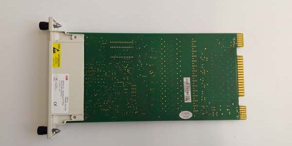
Product Core Brief
- Model: SPFEC12
- Brand: ABB
- Series: Symphony Plus / Bailey INFI 90 Harmony HR Rack I/O
- Core Function: Converts field analog sensor signals to digital data for bridge controllers via INFINET backplane bus
- Product Type: Rack-slotted high-precision analog input slave PCB
- Key Specs: 16 configurable AI channels | 16-bit ADC | 1500VAC per-channel galvanic isolation
- Note: Full platform end-of-life; only factory sealed new units and load-tested surplus available for legacy plant maintenance
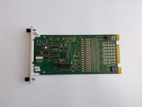
Key Technical Specifications
- Supported signal ranges: 4–20mA, 0–20mA, ±10VDC, 0–5VDC
- Channel configuration: Jumper selectable 16 single-ended or 8 differential inputs
- Full scale accuracy: ±0.1% FS at 25°C ambient
- Input impedance: ~250Ω for current loops, >1MΩ for voltage signals
- Backplane communication: Proprietary INFINET parallel bus
- Logic power source: 24VDC ±10% SELV from rack backplane
- Front indicators: Green POWER LED, red FAIL diagnostic LED
- PCB protection: ISA 71.04 G3 anti-corrosion conformal coating
- Operating temperature range: -10°C to +60°C inside sealed cabinets
- Max storage temperature: -40°C to +85°C
- Humidity rating: ≤75% RH non-condensing
- Isolation resistance minimum: 10MΩ between field circuits and backplane logic
Product Introduction
This unit mounts inside Harmony HR racks to collect continuous process readings from pressure, temperature, flow and level transmitters, then transmits scaled digital values to system bridge controllers. Its independent channel isolation eliminates ground loop drift common in multi-section industrial sites, and 16-bit conversion delivers tight measurement tolerances critical for closed-loop boiler and reactor control loops.
QA & Testing SOP
- Incoming Inspection: Cross-reference serial number against OEM spare database to filter counterfeit boards; inspect terminal blocks, backplane gold pins and conformal coating with a 10x magnifier for burn marks or corrosion; log serial numbers for full asset traceability.
- Live Testing: Seat the unit on a matching HR test rack paired with a SPBRC410 controller; connect a calibrated signal generator to all 16 channels; run a continuous 24-hour load cycle including wire break and short-circuit fault injection to validate diagnostic triggers.
- Electrical Testing: Use a Fluke 115 insulation tester to verify ≥10MΩ isolation between each field channel and rack ground; measure chassis PE continuity to confirm resistance below 0.5Ω.
- Firmware/Config Backup: Photograph internal single-ended/differential jumper positions; log factory calibration offset values printed on the PCB edge for field reference.
- Final QC & Packaging: Wipe PCB surfaces with static-dissipative microfiber cloth; cap all terminals and backplane connectors with insulating dust covers; seal the unit inside a shielding ESD bag, attach a printed QC tag with full 24-hour test timestamp, then pack into foam lined transit cartons.
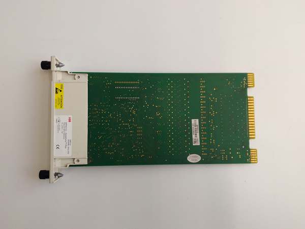
Installation Pitfalls & Guide
❗ Jumper misconfiguration creates permanent measurement offset: Always photograph jumper positions on the old unit before removal; mismatched single-ended/differential settings trigger constant FAIL LED alarms. ❗ Field wiring polarity reversal locks individual channels: Reverse 4–20mA transmitter leads activates current limiting protection, and the affected loop will not resume reading until wires are flipped and power cycled. ❗ ESD exposure risks irreparable ADC chip damage: Unwired bare finger contact with PCB traces can destroy high-precision sampling circuits; replacement boards cost thousands in downtime plus hardware expense. ❗ Hot-swap operation is forbidden: The backplane carries live 24VDC logic power; pulling the unit under power creates voltage transients that damage the rack bridge controller’s communication transceiver. ❗ Over-torqued terminal screws crack PCB copper traces: Follow OEM torque specs to avoid intermittent signal loss after weeks of thermal cycling.
4-step replacement guide
- Pre-install: Lock out and tag rack 24VDC auxiliary power; wait 10 minutes for internal capacitors to fully discharge; don ESD wrist strap; capture photos of all field terminal wiring and internal jumper layout.
- Removal: Disconnect all analog field wires channel by channel; release the front rack latch, slide the old unit straight out of the backplane slot without twisting.
- Install: Match jumpers on the new unit to the photos taken; align the board with rack slot rails and seat fully until the latch clicks; re-terminate all field wiring with specified torque values.
- Power-on Test: Restore rack 24VDC power; confirm steady green POWER LED; inject calibrated mid-scale signals to each channel to verify accurate DCS readings; simulate a wire break to confirm red FAIL LED activates and logs the correct channel number.
FAQ
Q: Can this unit operate without a bridge controller like SPBRC410? A: No. The device acts only as a passive signal converter and has no on-board logic processing. It relies entirely on the INFINET bus to exchange data with a compatible bridge CPU; no controller means no readable process values. Q: Is hot-swapping supported while rack power remains energized? A: It is not supported. The backplane bus carries live low-voltage logic signals, and unplugging the unit creates voltage spikes that can fry both the analog input board and the rack’s main controller communication chip. Full power lockout and capacitor discharge wait time are mandatory. Q: What warranty coverage applies to stocked units? A: Factory-new original boards carry a 12-month OEM warranty covering isolation circuits, ADC hardware and diagnostic LEDs. Load-tested surplus units come with a 6-month functional warranty. Damage from reversed field wiring, hot-swap removal or ungrounded ESD handling voids all coverage. Q: What upgrade replaces this obsolete hardware for new plant builds? A: ABB 800xA systems use S800 remote analog I/O modules with native Ethernet communication. A full DCS migration project is required to swap out legacy Symphony HR rack hardware, as bus protocols are incompatible. Q: Will stored calibration settings be lost after a full rack power outage? A: Calibration trim values are hard-set via passive resistor networks on the PCB, so power loss does not erase scaling offsets. Only custom jumper wiring configurations require manual reconfiguration after board replacement. Q: What are the most common failure modes for a faulty unit? A: Persistent red FAIL LED with intact field wiring, channel-to-channel signal crosstalk from degraded isolation transformers, consistent measurement drift under cabinet temperature swings, and complete loss of backplane communication with no visible physical damage to connectors.




