Product Core Brief
- Part Number: DS200TCRAG1ACC
- Brand: GE (GE Energy / GE Digital / GE Industrial Systems)
- Series: GE Speedtronic Mark V / DS200
- Core Function: TCRA relay output board that provides relay driver outputs within the Mark V turbine control system.
- Product Type: Mark V TCRA Relay Output Board
- Key Specs: Relay driver outputs | Mark V I/O core interface | 34-pin and 12-pin connectors documented for this part number family | legacy/obsolete product
- Condition: New Original / New Surplus
Product Introduction
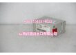
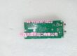
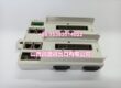
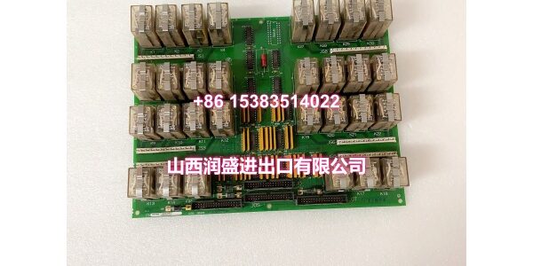
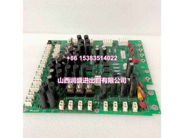
GE DS200TCRAG1ACC is a relay output board for the GE Speedtronic Mark V control system family. It is designed to provide relay driver outputs that allow the Mark V controller to command external relays, trip circuits, alarm circuits, or auxiliary control devices.
The board is commonly described as a relay output board used in industrial and turbine control applications. It converts controller signals into relay control outputs so that downstream electrical devices can be switched or monitored as part of the turbine protection and control logic.
Documented connector information for this part number includes a 34-pin connector and a 12-pin connector. However, public documentation for the exact DS200TCRAG1ACC suffix is limited, so the detailed relay channel count, coil voltage, contact ratings, LED indicators, jumper settings, and connector pinout should be verified from the physical board label and GE Mark V manuals.
Some third-party listings describe DS200TCRAG1ACC as an RST analog I/O board or associate it with TCQA analog signal conditioning functions. That conflicts with the relay output board description and should not be treated as authoritative without verification against the physical board label and GE documentation.
Key Technical Specifications
| Parameter | Value |
|---|---|
| Manufacturer | GE (GE Energy / GE Digital / GE Industrial Systems) |
| Part Number | |
| Product Type | TCRA Relay Output Board |
| Series | GE Speedtronic Mark V / DS200 |
| Typical Application | Relay driver output for turbine control and protection circuits |
| Connectors | 34-pin and 12-pin connectors documented |
| Output Type | Relay driver outputs |
| Relay Count | To be confirmed from physical board |
| Contact Rating | To be confirmed from physical board |
| Status | Legacy / Obsolete |
Note: The relay output function and 34-pin/12-pin connector configuration are documented for DS200TCRAG1ACC. The exact relay count, contact rating, coil voltage, LED indicators, jumper map, and ACC-specific configuration should be verified from the physical board label and GE Mark V manuals.
Quality Control Process (DYNAMIC GENERATION)
- Visual and label inspection. We check the part number, suffix, PCB surface, connectors, relay components, and mounting hardware for damage or corrosion.
- TCRA function verification. We confirm the board matches the DS200TCRAG1ACC relay output board description and is not mislabeled as a TCQA analog I/O board.
- Connector and continuity check. The 34-pin and 12-pin connectors are verified for correct pin continuity and no short circuits.
- Relay circuit inspection. Relay driver outputs and associated components are inspected for visible damage, burnt traces, or failed components.
- Final packaging. After passing inspection, the board is anti-static bagged and foam-packed for shipment.
Replacement Pitfall Guide (DYNAMIC GENERATION)
❗ Confirm TCRA function before installation. DS200TCRAG1ACC is a relay output board; do not substitute it with TCQA, TCEB, TCPD, SLCC, or other Mark V I/O boards.
❗ Ignore conflicting third-party descriptions. Some listings describe this part number as an analog I/O or TCQA-type board; that conflicts with the relay output board definition.
❗ Verify relay channel count and rating. Do not assume the relay count, coil voltage, or contact rating; confirm from the physical board before connecting load circuits.
❗ Label all connectors before removal. Miswiring relay outputs can cause incorrect trips, alarm failures, or equipment damage.
❗ Record jumper and LED status before removal. Document jumper positions and indicator states for troubleshooting reference after replacement.
❗ Check downstream trip/alarm logic. After replacement, verify that relay outputs operate correctly within the Mark V protection and control sequence.
❗ Handle as ESD-sensitive equipment. Always use anti-static wrist straps and handling procedures during removal, installation, and storage.
Keep these in mind and you’ll cut 90% of rework time.
Compatibility Matrix & Benchmarks
| Original Model | Replacement / Successor Model | Compatibility Level | Migration Notes |
|---|---|---|---|
| GE | GE | Direct | Same part number; verify relay count, contact rating, and connector pinout. |
| GE | GE DS200TCRAG1 variants | Needs Adaptation | Same TCRA family; suffix differences may affect revision or configuration. |
| GE | GE DS200TCRAG1ABC | Needs Adaptation | Same TCRA family; verify relay outputs and connector configuration before substitution. |
| GE | GE DS200TCQA / DS200TCQE | Not Compatible | TCQA/TCQE are analog I/O boards; not a direct replacement. |
| GE | Mark VIe / IS200/IS220 modules | Not Compatible | Different platform and architecture; not a direct replacement. |
Benchmark highlights
- GE Speedtronic Mark V TCRA relay output board.
- Provides relay driver outputs for turbine control and protection circuits.
- Documented with 34-pin and 12-pin connectors.
- Used within the Mark V I/O core to command external relays, trips, or alarms.
- Legacy product; best suited for existing Mark V system maintenance and like-for-like replacement.