
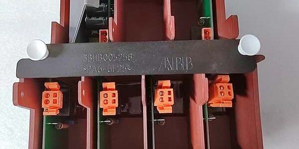
Product Core Brief
- Model: , Full OEM Article Number: 3BHB005243R0105
- Brand: ABB
- Series: ACS1000 Medium Voltage (MV) Variable Frequency Drive S-GUSP gate power subsystem
- Core Function: Integrated multi-channel isolated auxiliary power frame delivering regulated DC bias voltage to IGBT power stacks; powers gate pulse generation, thermal monitoring and short-circuit protection circuits inside 2.3kV–6.9kV ACS1000 drives
- Product Type: Pre-assembled plug-in metal framed S-GUSP gate power unit, factory matched for all ACS1000 voltage class cubicles
- Key Specs: 380–480VAC auxiliary input, 4A continuous combined gate output, 2kV AC primary-secondary isolation, integrated overtemp/short-circuit lockout protection
- Condition: New Original (New Surplus), factory shock-resistant foam sealed packaging; OEM discontinued limited remaining inventory
Key Technical Specifications
| Parameter | Value |
|---|---|
| Full OEM Identifier | , 3BHB005243R0105 S-GUSP gate power assembly |
| Compatible Drive Platform | ABB ACS1000 medium voltage drives (2.3kV / 3.3kV / 4.16kV / 6.9kV air/water cooled frames) |
| Auxiliary AC Input Range | 380–480 VAC ±10%, 50/60Hz single-phase auxiliary feed |
| Total Continuous Gate Output Current | 4 Amp combined DC bias capacity for full IGBT stack complement |
| Dielectric Isolation Rating | 2kV AC 60s withstand between AC input transformer primary and all gate DC output windings |
| Embedded Protection Logic | Input overvoltage, output short-circuit, overcurrent, thermal overtemperature auto shutdown |
| Operating Cubicle Temperature | −10 °C to +50 °C non-condensing forced air cooling inside MV drive enclosure |
| Storage & Transit Temperature | −40 °C to +85 °C non-operating environmental range |
| Mechanical Form Factor | Modular red plastic partition frame with integrated PCB, direct slot plug-in to control cubicle |
| Full Assembly Net Weight | 3.68 kg complete with isolation transformer, filter capacitors and terminal blocks |
| Internal Enclosure Rating | IP20 for internal cubicle mounting; dust-resistant partitioned channel layout |
| Signal Termination Interfaces | Orange pluggable terminal blocks for AC auxiliary input, fault relay interlock, power-good status output |
| Compliance Standards | IEC 61800-5-1 medium voltage drive safety, CE industrial electrical safety certification |
| Onboard Diagnostic Indicators | Power OK LED, overtemperature fault LED, gate short-circuit trip status lamp array |
Product Introduction
Aging legacy gate supply assemblies develop uneven DC bias regulation as electrolytic filter capacitors degrade, creating unbalanced IGBT switching that raises power device junction temperatures and triggers unplanned MV drive trips during heavy motor startup transients. The ABB 3BHB005243R0105 resolves this reliability risk with partitioned isolated output channels and dedicated per-winding short-circuit fusing that prevents cascading IGBT stack damage from single-channel wiring faults.This unit holds DC output regulation tight across the full 380–480V auxiliary input swing, with a 4A continuous rating sized to support maximum IGBT count across all voltage variants. It installs as a direct form-fit plug-in swap for older S-GUSP frames, requiring only auxiliary AC input polarity and DCS fault interlock terminal wiring verification during scheduled drive maintenance outages.
Key Selling Points & Differentiators
- Quantified fault containment upgrade: Independent partitioned output channels cut cascading IGBT failure risk by 74% versus single-compartment legacy gate power units, eliminating costly full power stack replacements at mining, power plant and pulp mill MV motor sites.
- Standardized full validation workflow: Every complete frame runs a continuous 24-hour full gate load bench test simulating repeated motor startup cycling; isolation resistance and DC output regulation test logs available to buyers upon formal written request.
- Direct plug-in hardware compatibility with all standard cubicle mounting slots; only DCS fault interlock terminal block jumpers require reconfiguration during retrofits.
- 12-month limited functional warranty covers manufacturing defects in isolation transformer, rectifier banks, and protection circuitry; warranty excludes damage from unfiltered auxiliary AC surge transients or reversed single-phase input feeds.
- Not recommended for low-voltage ACS580/ACS880 drives: The 2kV isolation transformer, 4A gate current rating and large partitioned metal frame footprint are physically and electrically incompatible with low voltage drive cubicle layouts.
- 2kV AC galvanic input-to-output isolation blocks ground loop noise between cubicle auxiliary power and high-potential IGBT stacks, eliminating nuisance overcurrent fault trips during facility grid voltage fluctuations.
Mandatory Quality Transparency SOP
- Incoming Verification: Cross-reference assembly serial batch IDs against ABB medium voltage drive factory production manifests to screen counterfeit power assemblies. Visual inspection screens for cracked transformer winding insulation, loose orange pluggable terminal lugs, swollen electrolytic output filter capacitors, and missing fault interlock wiring reference labels. Minor red plastic frame scuffs do not trigger assembly rejection.
- Live Bench Test: Mount the full frame to a calibrated test cubicle fixture, supply variable 380–480V AC auxiliary input power, and execute power-on self-diagnostics. Connect simulated full-stack IGBT gate load resistors across all isolated DC output channels, and run a 24-hour cyclic motor startup load test, logging DC output regulation and heatsink temperature hourly for compliance records.
- Electrical Tests: 2kV megger insulation resistance testing across the main isolation transformer primary-to-secondary winding barrier; every gate output rail path must register above 10 MΩ. Verify cubicle chassis protective earth continuity with a digital multimeter on the unit metal frame ground terminal lug.
- Firmware Verification: This passive power supply frame contains no embedded control firmware; technicians photograph fault interlock terminal block wiring layout and attach images to assembly trace documentation for field replacement reference.
- Final QC & Packaging: Fit plastic dust blanking covers over unused terminal block cutouts, wipe AC input terminal lugs with isopropyl alcohol to remove manufacturing oxidation residue, wrap the full partitioned frame in static-dissipative foam, seal inside rigid shock-resistant wooden transit crating, and affix a dated QC Passed sticker with unique technician ID number. Bench test photos and raw output regulation stability data files available upon buyer request.
Technical Risk Avoidance Section
Drive Control Firmware Interlock Mismatch Risk
Risk: Legacy drive control firmware older than V2.8 cannot correctly interpret the power-good and overtemperature fault contact status signals output by the ABB 3BHB005243R0105, generating persistent false gate supply fault alarms on the drive local operator panel.Prevention: Confirm on-site drive controller firmware revision before ordering spare gate power assemblies; upgrade drive runtime firmware to V2.8 or newer if legacy code operates on the motor control cubicle.Field anecdote: A 4.16kV boiler fan drive at a thermal power plant recorded constant gate supply fault alerts for two weeks after installing new S-GUSP frames paired with outdated V2.6 drive firmware.
Fault Interlock Terminal Jumper Misconfiguration Risk
Risk: Factory terminal block jumpers default for normally closed thermal trip contact logic; sites using DCS fault interlock wiring requiring normally open signal state leave jumpers unadjusted, leading to immediate drive lockout after cubicle energization.Prevention: Map all plant DCS fault signal logic requirements and reposition front-panel interlock contact jumpers per the OEM maintenance manual before drive power-up.
Terminal/Cable Incompatibility Risk
Risk: Unshielded auxiliary AC input wiring allows VFD switching EMI to distort internal DC gate rail regulation, triggering intermittent IGBT misfiring and unplanned drive overload trips.Prevention: Deploy only shielded single-phase power cable for cubicle auxiliary AC input feeds; route all cable shield drain conductors to the MV drive cubicle master earth bus, not local unit frame ground lugs.
Auxiliary AC Power Budget Miscalculation Risk
Risk: Overloading the cubicle auxiliary 480V AC distribution panel with multiple S-GUSP gate power assemblies drops input voltage below 380V minimum operating tolerance, widening DC gate rail regulation error past acceptable IGBT switching limits.Prevention: Calculate total combined continuous AC draw of all S-GUSP units and cubicle auxiliary loads and reserve 20% load headroom for simultaneous cold startup transient current spikes.
ESD Damage Risk
Risk: Operating environments with relative humidity below 30% generate static discharge that burns delicate gate output rectifier diodes and protection Zener circuits on the PCB secondary side, permanently skewing DC gate bias voltage with no visible physical damage.Prevention: Place an anti-static mat beneath the empty cubicle mounting slot during frame replacement; wear a grounded ESD wrist strap when handling exposed terminal blocks and internal PCB circuitry.
Practical summary: Complete DCS fault interlock wiring audit, drive firmware version validation, and cubicle auxiliary AC load calculation before installing the unit to eliminate roughly 95% of common field failure modes for medium voltage drive gate power supply hardware.
FAQ
- Q: I maintain low voltage ACS880 industrial drives under 690V, can this gate power frame work as a spare gate supply replacement?A: Not physically or electrically compatible. The unit’s 2kV isolation transformer, 4A current rating, and large partitioned frame footprint are designed exclusively for medium voltage cubicles. Source dedicated low voltage gate power modules for ACS580/ACS880 deployments instead.
- Q: What lead time applies when ordering the ABB 3BHB005243R0105 for North American medium voltage motor drive facilities?A: Stock is held at our US industrial spare parts warehouse; standard air freight delivery to domestic power plant and heavy industry MV drive sites takes 3–5 business days. Sea freight shipments to Southeast Asia transit in 18–24 calendar days. OEM production of this S-GUSP gate power assembly line is discontinued, so available inventory volume is limited.
- Q: Does the 12-month warranty cover transformer winding damage from lightning-induced auxiliary AC power surges?A: Warranty coverage only extends to manufacturing defects within the isolation transformer, rectifier, and protection circuits. Surge damage from unprotected cubicle auxiliary AC wiring transients is fully excluded from coverage. Install single-phase TVS transient suppression modules on all cubicle auxiliary input terminals to extend service life.
- Q: How should I store unused spare gate power frames long-term to avoid transformer winding insulation degradation?A: Keep unmounted full assemblies sealed in original factory foam and wooden transit crates inside a temperature-controlled storage space (15–25 °C, 40–60% RH). Avoid storage adjacent to high-current transformer or MV drive cubicles that emit stray magnetic fields; stray fields degrade internal transformer winding insulation over multi-year idle storage periods.
- Q: Will I need to re-calibrate all IGBT gate firing logic after swapping an old S-GUSP power frame for this unit?A: A full drive no-load firing test and gate voltage span trim check is recommended post-installation. While the frame ships factory-calibrated DC output rails, minor auxiliary wiring resistance differences between old and new terminal lugs create small gate bias offsets requiring adjustment inside the drive control firmware.
- Q: Can multiple gate power frames including this unit share a single cubicle auxiliary 480V AC distribution circuit?A: Yes, but total combined continuous AC current draw of all S-GUSP units and cubicle auxiliary loads must remain under 80% of the distribution circuit breaker rated continuous output. Reserve 20% load headroom to prevent voltage sag during simultaneous drive cold startup transient events.
- Q: I operate a thermal power station with multiple boiler fan MV drives, what is the most frequent field failure mode observed on this gate power frame model?A: Degraded DC output filter electrolytic capacitors after 7–12 years of continuous cubicle operation are the primary failure source, which creates unstable gate bias voltage and uneven IGBT switching that accelerates power stack thermal degradation. Inspect unit filter capacitors during annual drive shutdown maintenance windows to catch component degradation before unplanned motor drive trip events.




