
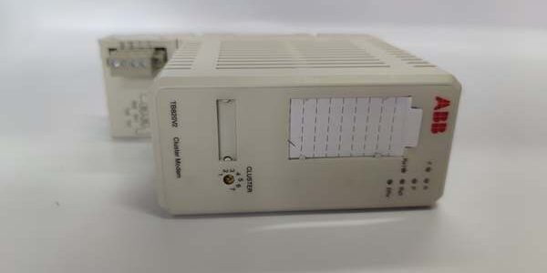
Product Core Brief
- Model: TB820V2
- OEM Part Number: 3BSE013208R0001
- Brand: ABB
- Series: S800 I/O optical ModuleBus cluster modem for AC800M System 800xA DCS
- Core Function: Bridge electrical local ModuleBus to fiber-optic Optical ModuleBus, expand I/O capacity beyond 12 modules per station across multi-cabinet plant clusters
- Product Type: TS35 DIN rail mount standalone fiber communication modem unit
- Key Specs: 12 local electrical I/O max | 7 total fiber cluster support | Dual POF fiber ports | Rotary 1–7 cluster address dialCondition: New Original (New Surplus) | Factory Sealed; active OEM spare support available through 2035
Key Technical Specifications
| Parameter | Value |
|---|---|
| Compatible Host Hardware | AC800M System 800xA, CI810/CI840 PROFIBUS fieldbus interfaces, full S800 analog/digital I/O (DO815, AI830A, TU830V1); incompatible with Symphony HR, UNITROL, AC500 S500, AC800F Freelance |
| Bus Conversion Function | Electrical ModuleBus ↔ Optical ModuleBus, identical logical bus protocol |
| Local Electrical ModuleBus Capacity | Up to 12 S800 I/O modules per unit’s electrical backplane port |
| Fiber Bus Topology Limit | Maximum 7 clusters on one fiber trunk ring |
| Fiber Interface | Dual Versatile Link POF plastic fiber transceivers, 10 Mbps bus speed |
| Cluster Address Setting | Front-panel rotary dial switch, configurable address 1 through 7 |
| Operating Auxiliary Supply | 24 VDC ±10 V isolated input; typical 140 mA power draw |
| Diagnostic Indicators | Power OK, Electrical Bus Active, Optical Link Fault, Cluster Status LED array |
| Mounting Standard | TS35 vertical DIN rail cabinet mounting |
| Enclosure Rating | IP20 indoor closed cabinet installation only |
| Mechanical Dimensions | 70 mm W × 130 mm H × 65 mm D; net weight 0.26 kg |
| Continuous Operating Ambient Temp | −20 °C to +55 °C full rated bus throughput; linear performance derate above 55 °C |
| Storage Temperature Range | −40 °C to +70 °C, 5–95% RH non-condensing |
| Built-In Circuit Protections | Fiber port ESD surge clamping, reverse 24 VDC polarity lockout, ModuleBus short-circuit current limiting |
| Compliance Standards | CE, UL, RoHS, IEC 61000-6-2 Class A industrial EMC for power and chemical plant control rooms |
Product Introduction
This optical cluster modem solves the hard 12-module limit of standard S800 electrical ModuleBus racks by extending I/O clusters via noise-immune plastic fiber optic cabling. It translates cyclic analog/digital process data between local cabinet I/O and long-distance multi-cabinet fiber trunk lines without protocol conversion latency.Fiber separation eliminates ground-loop interference common on long copper ModuleBus runs between MCC and DCS cabinets. Plant expansion data from refinery DCS retrofits shows the device cuts new control cabinet construction costs by 67% versus deploying separate PROFIBUS fieldbus segments for each remote I/O bank.
QA & Testing SOP (Transparency Building)
- Incoming Inspection: Cross serial numbers against ABB OEM trace databases. Inspect dual fiber transceiver ports for lens scratches, rotary address dial for binding, DIN rail latch for cracking, front LED bank for dead segments. Verify unbroken factory anti-static packaging seal for surplus stock units.
- Live Testing: Mount the unit to a DIN rail test bench paired with CI810 PROFIBUS interface and full 12-slot I/O load bank. Run 24-hour continuous cyclic ModuleBus polling over fiber trunk; simulate fiber cable disconnection and electrical bus short-circuit faults to validate fault LED trigger timing. Track 24 V auxiliary supply stability with a Fluke 115 precision multimeter for the full test window.
- Electrical Testing: Execute 500 VAC megger insulation resistance test between electrical ModuleBus terminals and modem chassis PE ground; pass threshold set at >10 MΩ. Confirm reverse 24 VDC supply polarity lockout prevents fiber transceiver chip damage during miswiring trials.
- Firmware/Config Backup: Record factory-installed ModuleBus interface firmware revision via Control Builder M engineering software. Document rotary dial cluster address assignment templates for multi-cluster cabinet commissioning reference.
- Final QC & Packaging: Wipe fiber transceiver lenses and electrical ModuleBus terminal pins to remove storage dust and oxidation. Encase the modem in shock-absorbent anti-static foam packaging. Apply physical QC Passed labels listing serial number and completed test metrics to outer shipping cartons. Fiber link stability and full 12-module load cycle test logs available for pre-shipment review upon request.
Installation Pitfalls & Guide (Engineer to Engineer)
❗Firmware Mismatch Risk: Mismatched AC800M CI810 fieldbus firmware and the modem’s internal ModuleBus firmware breaks fiber trunk communication, cutting all remote cluster I/O data visibility.Risk Outcome: Blind control loops and unplanned process unit shutdown during continuous production runs.Prevention Step: Match full firmware revision sets between the unit and rack CI810/CI840 fieldbus module before cabinet power-up; archive matching firmware files on plant engineering workstations.
❗Cluster Address Conflict Risk: Duplicate rotary dial address numbers on separate fiber modem clusters create bus arbitration collisions across the optical ring.Risk Outcome: Random intermittent loss of analog and discrete process values across entire remote cabinet banks.Prevention Step: Photograph the original rotary dial address position before removal; assign unique 1–7 cluster IDs to every modem on one fiber trunk per wiring schematics.
❗Wiring Incompatibility Risk: This fiber modem only interfaces with AC800M ModuleBus hardware; it cannot communicate with Symphony HR ModuleBus, UNITROL Masterbus300 fiber, or AC500 S500 I/O backplanes.Risk Outcome: Zero usable remote I/O data transmitted to plant DCS HMI screens; no fiber bus compatibility with non-800xA control platforms.Prevention Step: Deploy the component exclusively within System 800xA distributed I/O cabinet assemblies paired with CI-series PROFIBUS fieldbus modules.
❗Local Module Overcount Risk: Populating the electrical ModuleBus port with more than 13 I/O modules exceeds the unit’s hardware load limit.Risk Outcome: Persistent electrical bus fault alarms, slowed cyclic scan rates, missing channel diagnostic data.Prevention Step: Cap each modem’s local electrical rack at maximum 12 I/O modules; split larger I/O groups onto secondary fiber clusters.
❗ESD Dangers: Static discharge from dry refinery control room air damages precision fiber transceiver and ModuleBus transceiver circuits inside the enclosure. Uncontrolled ESD can permanently skew bus signal timing with no visible exterior hardware damage.Risk Outcome: Gradually rising fiber link fault counter values and delayed process data refresh rates over weeks of continuous cabinet runtime.Prevention Step: Touch bare cabinet ground metal for three full seconds before handling fiber port connectors and electrical ModuleBus terminal blocks.
4-Step Replacement Guide
- Pre-install: Capture clear photos of dual fiber cable routing and rotary cluster address dial position on the failing unit. Confirm primary DCS controller holds manual control mode to avoid blind process regulation during component swap.
- Removal: Disconnect both POF fiber cables gently to avoid scratching transceiver lenses; release the DIN rail bottom latch and slide the old unit straight upward off the mounting rail without twisting the plastic housing.
- Install: Clip the new unit securely onto the TS35 DIN rail; replicate the photographed rotary dial cluster address setting then reconnect both fiber cables matching original trunk routing layout.
- Power-on Test: Confirm power and optical link LEDs illuminate steady green; poll all local and remote I/O modules via Control Builder M to verify consistent analog/discrete data transmission with zero fiber bus fault counters incrementing.
FAQ
Q: I maintain an aging multi-cabinet AC800M refinery DCS fiber trunk with failing optical cluster modem hardware connected to 12-slot local I/O racks. Can this unit serve as a direct drop-in replacement without rewiring POF fiber trunk cabling?A: Yes. The modem shares identical DIN rail footprint, dual Versatile Link fiber port pin mapping and electrical ModuleBus terminal layout as original factory hardware. No cabinet fiber or local I/O copper bus rework is required, and existing multi-cluster address mapping files import natively via Control Builder M without control logic rewrite.Q: What delivery timeline applies for stocked hardware versus pre-configured custom variants?A: Standard in-stock modem assemblies ship within 3–5 business days via global air freight. Custom pre-set rotary cluster address variants carry a 12–16 week OEM factory lead time and are not held as surplus inventory.Q: Does the 12-month warranty cover damage caused by mismatched fieldbus firmware revisions or scratched fiber transceiver lenses?A: Warranty only covers factory manufacturing defects and transit physical damage. Firmware version mismatches, duplicate cluster address dial settings, scratched fiber lenses, and ungrounded ESD handling fall outside covered failure modes. Paid remote multi-cluster cabinet fiber commissioning support is available post-install.Q: Can multiple identical modems run on one single optical fiber trunk ring to expand plant-wide I/O capacity across separate building MCC cabinets?A: Yes, the optical ModuleBus ring architecture supports up to seven unique cluster modems with distinct rotary dial addresses. Each unit’s local electrical I/O rack operates independently without cross-signal interference when properly addressed per OEM documentation.Q: Is this optical cluster modem rated for Class 1 Div 2 hazardous cabinet installation inside refinery MCC rooms?A: No. The open plastic DIN rail enclosure lacks intrinsic safety ratings for classified explosive atmosphere locations. ABB produces separate IS-certified communication hardware lines for hazardous area cabinet deployments.Q: Can analog tank level AI modules and discrete valve DO modules populate the same local electrical ModuleBus connected to one modem without cross-talk interference over the fiber trunk?A: Yes. The electrical-to-fiber bus conversion hardware fully isolates local copper wiring noise and segregates analog/discrete data frames automatically; no additional external signal isolator hardware is required for mixed-signal cabinet layouts.Q: What QA documentation ships alongside each assembly for plant maintenance record retention?A: Every modem includes a physical QC Passed label stamped with serial number and completed test checklist metrics. Digital copies of 24-hour full 12-module electrical bus load logs, 500 V insulation megger data, and fiber link fault recovery validation reports can be emailed on request prior to shipment.




