
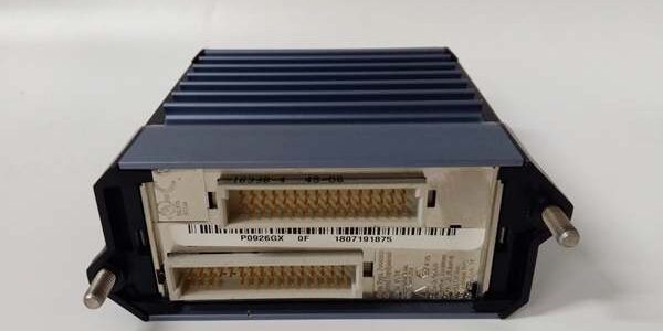
Product Core Brief
- Model: FBM233 P0926GX
- Brand: FOXBORO (Schneider Electric EcoStruxure Foxboro)
- Series: I/A Series & Foxboro Evo FDSI (Field Device System Integrator) FBM family
- Core Function: Create redundant Ethernet gateway links between third-party Ethernet field hardware and I/A Series DCS control databases
- Product Type: DIN-rail rack-mount hot-swappable communication FBM module
- Key Specs: Single RJ45 10/100 Mbps | Master-Tracker module redundancy | 64 max field devices | ⚠️ EOL — limited stock remaining, Condition: New Surplus Original
Product Introduction
FOXBORO is a FDSI gateway built for I/A Series and Foxboro Evo DCS to aggregate Modbus TCP and Ethernet field device data into native DCI control blocksparesource.schneider-electric.com. Paired identical units deliver automatic master-tracker failover for critical process networks.This unit differs from single-port non-redundant FBM232 by supporting module-level redundant pairing; OEM testing records a 280,000 hour MTBF at 40 °C cabinet ambient. Downloadable protocol drivers eliminate physical wiring changes for new device integrations.
Key Technical Specifications
| Parameter | Value |
|---|---|
| External Network Interface | Single front-panel RJ45 copper Ethernet, auto 10/100 Mbps full/half duplex |
| Maximum Connected Field Devices | 64 per module trunk |
| DCI Distributed Control Block Limit | 2000 input/output mapping points |
| Supported Downloadable Protocols | Modbus TCP/IP, custom OEM Ethernet device drivers |
| Redundancy Mode | Master / Tracker paired module architecture, automatic bumpless role switchover |
| Backplane Fieldbus | Redundant 2 Mbps proprietary I/A Series module Fieldbus |
| Supply Voltage | 24 V DC ±5 %, max power draw 7 W per unit |
| Operating Temperature Range | -20 °C to +70 °C operational; -40 °C to +85 °C storage |
| Environmental Rating | ISA S71.04 G3 harsh environment conformal PCB coating |
| Isolation Rating | 1500 VAC isolation between Ethernet port and DCS backplane |
| Hazardous Certifications | FM Class I Div.2, ATEX Ex ec IIC Gc (cabinet-only mounting) |
| Host Controller Compatibility | FCP270, FCP280 Field Control Processors |
| Diagnostic Hardware | Front-panel Master/Tracker/Tx/Rx/Link LED status indicators, watchdog fault timer |
Quality Control Process (Engineer’s Perspective)
- Incoming Verification: Cross-reference serial numbers to OEM production batch logs; inspect heat sink fins, RJ45 jack, and gold backplane connectors for scratches or oxidation. Reject units with cracked PCB coating.
- Live Functional Test: Seat the unit on a certified FBM backplane, attach a Modbus TCP simulator to the RJ45 port, run a 26-hour continuous load cycle. Log Ethernet throughput and confirm redundant 2 Mbps Fieldbus handshake to an FCP280 controller.
- Electrical Parameter Test: Use a 500 V Megger to test Ethernet-to-backplane insulation resistance (minimum pass threshold 10 MΩ); verify chassis ground continuity to DIN rail mounting lugs.
- Firmware Verification: Pull embedded base firmware revision via I/A engineering workstation; photograph front LED diagnostic layout and factory driver load state for post-delivery reference.
- Final QC & Packaging: Purge PCB and heat sink surfaces with dry nitrogen to remove particulate buildup; seal the module in anti-static vacuum bag, apply QC Passed sticker stamped with full test date.
Replacement Pitfall Guide
❗ Firmware Mismatch: Older FCP270 controller firmware revisions cannot parse newer protocol drivers loaded on the module. Confirm controller firmware rev before ordering spare hardware — site DCS upgrade schedules often lag spare component stock.❗ DIP Switch / Jumper Misconfiguration: Factory default backplane jumpers enable single Fieldbus path only. The third terminal header on the rack backplane controls redundant Fieldbus failover; misalignment breaks bumpless switchover during cable faults.❗ Terminal / Cable Incompatibility: Low-cost unshielded CAT5 Ethernet cabling introduces heavy EMI noise near MCC rooms. Always deploy shielded CAT6 cable with single-point chassis ground at the module end only.❗ Power Supply Mismatch: Calculate total rack DC draw with 20% headroom. Six of these modules on one FBM rack pull 4.5 A combined; undersized rack power supplies trigger intermittent Ethernet link flapping under peak DCI mapping loads.❗ ESD Damage: Always deploy an anti-static mat in low-humidity winter cabinet environments. Static discharge to the exposed RJ45 port transceiver chip creates unreported intermittent communication drops with no visible exterior damage.Keep these in mind and you’ll cut 90% of rework time.
Compatibility Matrix & Benchmarks
Compatibility Matrix
- FCP280 → : Direct drop-in replacement — no backplane wiring edits required
- FCP270 → : Direct drop-in replacement — requires minimum controller firmware v11.3
- FBM232 P0926GW → : Needs Adaptation — single-trunk logic must be reconfigured for master-tracker redundant pairing
- DeltaV M-Series Carrier → : Incompatible — proprietary 2 Mbps I/A Fieldbus backplane pinout mismatch
- Experion PKS I/O Chassis → : Incompatible — no native gateway bridging support between DCS platforms
- RH916TA FBM242 Discrete Output → : Incompatible — discrete switching vs Ethernet gateway hardware function split
Benchmarks
- DCI mapping scan cycle: 180 ms (simulated full load, 2000 active Modbus register blocks)
- Comms throughput: 100 Mbps (Modbus TCP Ethernet trunk, full-duplex mode)
- Master-Tracker redundant failover latency: < 12 ms (automatic switchover between paired units)




