
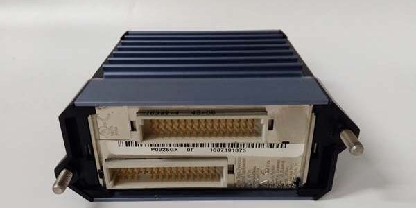
Product Core Brief
- Model: FBM201
- Brand: FOXBORO (Schneider Electric EcoStruxure Foxboro)
- Series: I/A Series Compact 200 FBM analog I/O family
- Core Function: Digitize 0–20 mA field transmitter signals and deliver isolated measurement data to I/A Series FCP controllers
- Product Type: Rack-mount hot-swappable analog input FBM paired with termination assembly
- Key Specs: 8 fully isolated channels | HART transparent support | independent Sigma-Delta ADC | ⚠️ EOL — limited stock remaining, Condition: New Surplus Original
Product Introduction
FOXBORO is a compact analog input assembly built for I/A Series and Foxboro Evo DCS to collect two-wire transmitter 4–20 mA signals via the matched terminal base. Every channel carries independent galvanic isolation to suppress plant EMI noise.This unit differs from voltage/millivolt variants by natively supporting HART FSK communication, with OEM-measured MTBF of 335,000 hours at 40 °C cabinet ambient. The base integrates standardized screw terminals to streamline field wiring marshalling.
Key Technical Specifications
| Parameter | Value |
|---|---|
| Input Channel Count | 8 independent galvanically isolated analog inputs |
| Nominal Input Signal Range | 0–20 mA DC (4–20 mA transmitter compliant) |
| Per-Channel ADC Type | Independent Sigma-Delta converter, 25 ms fixed base sample rate |
| Static Measurement Accuracy | ±0.03% full span (0 °C to 60 °C cabinet range) |
| Temperature Coefficient | ±50 ppm/°C measurement drift |
| Channel Isolation Withstand | 600 VAC channel-to-channel / channel-to-ground 1-minute rating |
| Input Channel Impedance | 61.5 Ω nominal |
| HART Compatibility | Transparent FSK pass-through for HART 5/7 smart transmitters |
| Common Mode Rejection Ratio | >100 dB at 50 / 60 Hz industrial mains noise |
| Normal Mode Rejection Ratio | >95 dB at 50 / 60 Hz |
| Module Power Consumption | Max 7 W total draw from 24 V DC backplane supply |
| Operating Temperature Range | -20 °C to +70 °C operational; -40 °C to +85 °C storage |
| Environmental Coating | ISA S71.04 G3 full PCB conformal coating |
| Hazardous Certifications | FM Class I Div.2, ATEX Ex ec IIC Gc (cabinet-only mounting) |
| Termination Hardware | anti-vibration screw-clamp TA assembly |
| Backplane Bus | Redundant 2 Mbps proprietary I/A Series module Fieldbus |
Quality Control Process (Engineer’s Perspective)
- Incoming Verification: Cross-match serial numbers on card and base to OEM batch logs; inspect terminal threads, gold backplane connectors, and PCB coating for scratches or oxidation. Reject assemblies with cracked isolation barriers.
- Live Functional Test: Mate the paired unit to a certified Compact 200 backplane, connect a precision 0–20 mA signal generator to terminals, run a 26-hour continuous signal cycle. Log channel temperature and confirm redundant 2 Mbps Fieldbus handshake to an FCP280 controller.
- Electrical Parameter Test: Use a 500 V Megger to test channel-to-backplane insulation resistance (minimum pass threshold 10 MΩ); verify chassis ground continuity to DIN rail lugs on the base.
- Firmware Verification: Extract embedded FBM firmware revision via I/A engineering workstation; photograph terminal pin layout and factory DIP switch default positions for post-delivery reference.
- Final QC & Packaging: Purge FBM and TA PCB surfaces with dry nitrogen to remove industrial dust buildup; seal both components in separate anti-static vacuum bags, apply matching QC Passed stickers stamped with full test completion date.
Replacement Pitfall Guide
❗ Firmware Mismatch: Older FCP270 controller firmware revisions lack full HART polling support for the module. Confirm controller firmware rev before ordering spare assemblies — site DCS upgrade schedules often lag spare component stock.❗ DIP Switch / Jumper Misconfiguration: Factory default backplane jumpers disable redundant Fieldbus paths. The second header on the base controls loop power feed polarity; reversed wiring burns front-end ADC chips instantly.❗ Terminal / Cable Incompatibility: 18 AWG thin wiring on terminals creates excessive voltage drop for long transmitter runs. Use minimum 16 AWG shielded twisted pair for field cable lengths over 20 m.❗ Power Supply Mismatch: Calculate total rack DC draw with 20% headroom. Four of these paired assemblies on one Compact 200 backplane pull 28 W combined; undersized rack power supplies trigger intermittent signal dropouts under full transmitter load.❗ ESD Damage: Always deploy an anti-static mat in low-humidity winter cabinet environments. Static discharge to exposed gold backplane connectors destroys channel isolation circuits with no visible exterior damage to the FBM or base.Keep these in mind and you’ll cut 90% of rework time.
Compatibility Matrix & Benchmarks
Compatibility Matrix
- FCP280 Controller → : Direct drop-in replacement — no backplane or TA wiring edits required
- FCP270 Controller → : Direct drop-in replacement — requires minimum controller firmware v11.0
- FBM201b mV Input Card → : Needs Adaptation — field signal wiring and workstation channel scaling must be reconfigured
- FBM232 P0926GW Ethernet Gateway → : Incompatible — communication gateway vs analog acquisition hardware function split
- DeltaV M-Series Carrier → : Incompatible — proprietary 2 Mbps I/A Fieldbus backplane pinout mismatch
- Experion PKS I/O Chassis → : Incompatible — no native Compact 200 backplane support
Benchmarks
- Analog measurement scan cycle: 200 ms (simulated full load, 8 HART 4–20 mA transmitters active)
- Comms throughput: 2 Mbps (redundant I/A proprietary Fieldbus backplane protocol)
- HART diagnostic poll interval: 5 seconds per channel (software configurable upper limit)




