Product Core Brief
- Model: SST-PB3-VME-2-E
- Brand: Molex Woodhead SST (BradCommunications)
- Series: SST-PB3 VME PROFIBUS scanner card family
- Core Function: Run two fully independent galvanically isolated PROFIBUS DP master channels with dedicated co-processors; exchange cyclic I/O and diagnostic data between VME host CPUs and PROFIBUS slave hardware including Rexroth servo drives and tightening controllers.
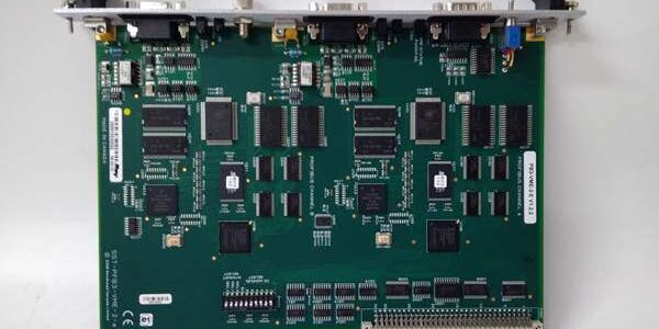
- Product Type: Single-slot 6U VME64 Eurocard with dual front D-SUB9 PROFIBUS ports and RS232 local service port; E suffix denotes extended wide temperature rating and reinforced galvanic isolation
- Key Specs: Two isolated PROFIBUS channels | 512 KB RAM / 512 KB flash per channel | 1500 V AC channel-to-chassis isolation | Operating range -40 °C to +70 °C | Max 122 DP slaves per port | Condition: Refurbished Load-Tested Surplus
- Suffix breakdown: PB3 = 3rd-gen PROFIBUS co-processor; VME = VME64 bus form factor; 2 = dual independent PROFIBUS networks; E = Extended wide industrial temperature + enhanced isolation hardware variant
Product Introduction
inserts into standard VME64 chassis to operate two physically separated PROFIBUS DP networks simultaneously, offloading all protocol processing from the VME host CPU via dedicated per-channel co-processors. It connects VME machine controllers to Rexroth HCS, HMD, SE311, and LT304 PROFIBUS slave assemblies without cross-bus bandwidth conflict.This unit differentiates from standard non-E variants by extending operating temperature limits and boosting galvanic isolation from 500 V AC to 1500 V AC for harsh cabinet environments. OEM field data records its rated MTBF above 100,000 operating hours under continuous 24/7 runtime at 50 °C cabinet ambient.
Key Technical Specifications
| Parameter | Value |
|---|---|
| VME Bus Compliance | VME64 single slot A24/D16/D32 addressing; 16 MB configurable VME memory window |
| VME Backplane Power Draw | 800 mA @ 5 V DC primary rail; 12 mA @ 24 V auxiliary sense input |
| Per-Channel Onboard Memory | 512 KB shared cyclic data RAM; 512 KB non-volatile flash for firmware and network config |
| PROFIBUS Physical Interface | Dual independent RS485 D-SUB9 female ports; 1500 V AC galvanic isolation per channel to chassis |
| Service Debug Port | Front RS232 9-pin D-SUB for local firmware flashing and offline network editing |
| Supported PROFIBUS Modes | DP-V0 Class1/Class2 Master; DP-V1 Class1/Class2 Master; single channel can run master + slave concurrently |
| Per-Channel Network Capacity | Maximum 122 PROFIBUS DP slave nodes; 244 input / 244 output bytes cyclic I/O mapping per slave |
| Host Interrupt Control | VME IRQ levels 1 through 7, fully configurable via on-board S1 DIP switch bank |
| Diagnostic Indicators | Two dedicated LED banks (OK / COMM / FAULT) for Channel A and Channel B independent status reporting |
| Mechanical Dimensions | VME single slot 6U × 1TE form factor; net unit weight 0.5 kg |
| Continuous Operating Ambient Temp | -40 °C to +70 °C full rated throughput; linear performance derate above +70 °C (verify with OEM datasheet) |
| Storage / Transport Temperature | -40 °C to +85 °C, non-condensing 5–95 % RH humidity range |
| Integrated Protection Circuits | RS485 bus short-circuit clamping, high-voltage channel isolation, reverse VME power polarity lockout |
| Compliance Certifications | CE, UL Class 1 Div 2 hazardous location qualified, RoHS, EN61000 Class A industrial EMC filtering |
| Supported Commissioning Software | SST PROFIBUS Configuration Tool, VME host driver libraries for VxWorks / Linux real-time OS |
Quality Control Process (Engineer’s Perspective)
- Incoming Verification: Cross-reference serial number against Molex Woodhead OEM part databases; inspect dual front D-SUB9 and RS232 port pins for bending, VME backplane edge connector for oxidation, and status LEDs for dead segments. Photograph front port pinout and DIP switch layout for field rack wiring reference.
- Live Functional Test: Insert card into VME64 test chassis paired with real-time VME host CPU and simulated Rexroth PROFIBUS slave drive stacks; run 24 hour cyclic I/O data exchange profiles at maximum 12 Mbps baud rate on both channels simultaneously. Use a Fluke 115 signal logger to track VME backplane current draw and dual-channel data transfer latency consistency.
- Electrical Parameter Test: 1500 V Megger isolation test between each PROFIBUS RS485 circuit and module chassis ground (pass threshold >10 MΩ); verify no cross-talk leakage between Channel A and Channel B isolated transceivers.
- Dual Channel & Firmware Verification: Flash factory standard firmware to each channel via RS232 service port; upload separate PROFIBUS network maps for Channel A and Channel B, retain full slave configuration tables over a 12 hour VME chassis power-off cycle to validate flash memory retention.
- Final QC & Packaging: Clean VME backplane edge connector contacts during refurbishment cycles; fit plastic protective caps over all three front D-SUB ports, seal unit in anti-static PE foam bag, apply dated QC Pass label listing dual-channel throughput, high-voltage isolation resistance, and independent fault detection test metrics before rigid carton shipping.
Replacement Pitfall Guide
❗ Photograph original dual D-SUB trunk wiring termination before module removal to preserve 120 Ω bus resistor placement on each network.❗ VME DIP Switch Address & IRQ Conflict Hazard: The S1 DIP switch bank sets VME memory window base address and interrupt level. Unmatched DIP switch settings create bus address collisions that crash the VME host CPU within seconds of power-up. Record all original DIP switch positions before extracting the module from the rack.❗ Dual Channel Bus Termination Miswiring Risk: Each PROFIBUS channel requires independent 120 Ω termination resistors enabled only at the two physical cable ends of each trunk. Shared termination between Channel A and Channel B creates signal reflection noise that triggers intermittent slave dropout at baud rates above 500 kbps.❗ VME Chassis Condensation Short-Circuit Risk: Cold-stored modules moved into warm humid control enclosures form PCB trace condensation within two hours. Allow minimum four-hour temperature acclimation before inserting into powered VME racks to prevent flash memory corruption and RS485 transceiver permanent failure.❗ ESD Co-Processor Circuit Damage: Onboard flash memory and PROFIBUS ASIC circuits carry low electrostatic discharge tolerance. Always rest the unit on a grounded anti-static mat during VME rack insertion or front port cable rewiring, especially in low-humidity cleanroom production environments.Keep these in mind and you’ll cut 90% of rework time.
Compatibility Matrix & Benchmarks
Compatibility Matrix
- non-standar : Needs Adaptation — no wiring changes required, update machine thermal monitoring logic to account for expanded -40 °C low-temperature operating window
- CML40.2-SP-330-NA-NNNN-NW Rexr : Direct — PROFIBUS DP slave mode enables bidirectional motion setpoint and fault data exchange via either Channel A or Channel B trunk
- HCS02.1E-W0028-A-03-NNNN i : Direct — native PROFIBUS DP slave port on drive connects to either isolated D-SUB trunk without external signal conditioning
- SE311 Rexroth tighte : Direct — onboard PROFIBUS interface maps torque-angle fastening recipe data to VME host shared memory buffers