Field technicians pairing standard DI cards with magnetic speed pickups produce unstable RPM readings from low-amplitude sine-wave pulses. Unfiltered EMI from adjacent MCC cabling triggers random false over-speed ESD trips during compressor load swings.
Where you’ll typically find it:
Refinery steam turbine ESD cabinets monitoring turbine shaft speed via gear-tooth magnetic pickups
Natural gas compressor HIPPS racks tracking high-speed crankshaft pulse for overpressure shutdown logic
Coal power boiler feed pump safety panels for overspeed protection interlock signaling
AC-coupled input design filters DC offset drift and eliminates false pulse counts to keep safety interlock integrity intact across wide site temperature shifts.
Hardware Architecture & Under-the-Hood Logic
Three fully separate isolated PCB processing legs run parallel pulse sampling; no shared analog circuitry between TMR cores to limit single-component failure exposure.
Incoming field pulse passes channel-specific AC coupling cap to strip unwanted DC bias before splitting equally to three isolated front-end amplifiers.
Each redundant leg converts analog pulse to digital count via independent onboard counter IC, no shared clock across tri-core layout.
Three raw pulse count values feed hardware voter circuit; 2-out-of-3 majority value locks in final channel reading for backplane transmission.
Onboard diagnostic circuit continuously checks for open/short field wiring, flags individual channel fault to front-panel LED and TriStation diagnostic buffer.
Valid voted data transfers across isolated backplane interface to Tricon main processor for safety logic execution.
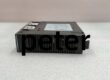
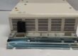
TRICONEX 3511
Field Service Pitfalls: What Rookies Get Wrong
Improper Magnetic Pickup Air Gap SettingNew tech sets pickup-to-gear gap too wide; output sine-wave amplitude drops below 1.5Vpp module trigger threshold leading to intermittent missing pulse counts and erratic RPM drift on trending screens.
Quick Fix: Set pickup gap 0.8mm–1.2mm per OEM datasheet; bench test sensor output with multimeter AC mV before landing to 3511 terminals.
Dual-End Shield Grounding Pulse Trunk CableInstaller grounds pickup cable braided shield both at field sensor terminal and cabinet marshalling ground rail; site ground potential difference creates circulating loop noise flooding pulse input with false spikes.
Field Rule: Shield bonded only at control room cabinet ground bar; field device end shield remains fully insulated floating.
Mixing DC-Coupled DI Wiring to 3511 Pulse TerminalsTech reuses existing dry-contact DI wiring for magnetic pickup feeds; residual DC voltage saturates AC-coupled input stage, permanently blanking all channel pulse detection.
Field Rule: 3511 requires dedicated twisted shielded pulse cable; never repurpose standard discrete DI field wiring runs.
Commercial Availability & Pricing Note
Please note: The listed price is for reference only and is not binding. Final pricing and terms are subject to negotiation based on current market conditions and availability.

")