Product Core Brief
- Model: DS200SDCIG1ABA
- Brand: GE (General Electric / GE Speedtronic family)
- Series: Mark V DS200
- Core Function: SDCI DC power and instrumentation board that provides logic power and interface circuits for DC2000 drive systems.
- Product Type: DC Power and Instrumentation Board (SDCI)
- Key Specs: Logic power supply for DC2000 drives | input voltage up to 600 VAC | JP1 MD control source jumper | MA/MD contactor drive interface | onboard LED and fuse indicators | replacement governed by GEI-100173
- Condition: New Surplus / Refurbished (legacy/discontinued board; confirm revision, jumper settings, and compatible drive cabinet)
Product Introduction
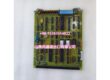
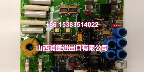
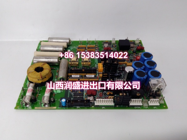
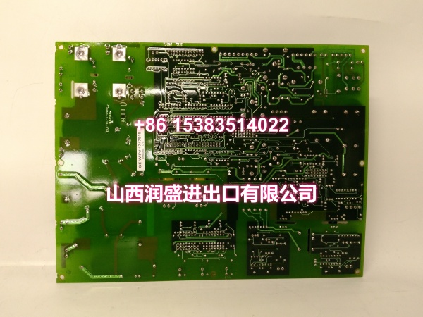
The GE DS200SDCIG1ABA is an SDCI DC Power and Instrumentation Board from the GE Speedtronic Mark V DS200 series. It serves as an interface board for DC2000 drive systems, providing logic power and associated interface circuits for drive cabinet operation.
The board supports input voltages up to 600 VAC and includes onboard LED indicators and fuse protection for diagnostic purposes. A key configuration feature is the JP1 jumper, which acts as the MD control source jumper. When configured, it allows the MD contactor drive hardware output to be slaved to the MA contactor drive hardware output. By default, the MD contactor drive output can also be controlled independently through MCP software.
The DS200SDCIG1ABA is referenced in GE’s SDCI DC Power and Instrumentation Board Replacement Procedures manual (GEI-100173). Because it is a discontinued Mark V component, replacement should follow the drive cabinet documentation, verified jumper configuration, and proper lockout/tagout procedures.
Key Technical Specifications
| Parameter | Value |
|---|---|
| Product Type | DC Power and Instrumentation Board (SDCI) |
| Brand | GE (Speedtronic Mark V) |
| Model | |
| Series | Mark V DS200 |
| Typical Application | DC2000 drive logic power and interface |
| Input Voltage | Up to 600 VAC |
| Jumper JP1 | MD control source (MA/MD contactor drive) |
| Diagnostics | Onboard LED and fuse indicators |
| Reference Manual | GEI-100173 |
| Status | Legacy / Discontinued |
Exact connector pinout, cabinet slot, and compatible drive frame must be confirmed from the board label and OEM manual.
Quality Control Process (DYNAMIC GENERATION)
- Part-number verification: Confirm DS200SDCIG1ABA and ABA revision on the board label.
- Visual inspection: Check connectors, fuses, LED indicators, JP1 jumper, and PCB traces for corrosion, burns, or mechanical damage.
- Jumper configuration review: Verify JP1 MD control source setting matches the original board or drive cabinet documentation.
- Fuse and LED check: Confirm onboard fuses are intact and LED indicators function correctly during power-up.
- Connector integrity check: Inspect power and signal connectors for bent pins, oxidation, or poor contact.
- Drive cabinet compatibility check: Confirm the board matches the installed DC2000 drive cabinet configuration.
Replacement Pitfall Guide (DYNAMIC GENERATION)
❗ Do not confuse SDCI with SDCC, PCCA, LDCC, or DCFB boards. DS200SDCIG1ABA is a DC power and instrumentation board, not a drive control card, power connection card, relay terminal board, or DC feedback board.
❗ Copy JP1 jumper setting before removal. The JP1 MD control source jumper determines whether the MD contactor drive is slaved to MA or independently controlled; incorrect settings can cause contactor sequencing faults.
❗ Follow proper lockout/tagout procedures. The board interfaces with up to 600 VAC input; all power must be removed and verified de-energized before handling.
❗ Do not hot-swap connections. Never remove or insert connectors while the board or drive is energized; this can cause equipment damage.
❗ Verify LED/fuse diagnostics. A lit LED may indicate a blown fuse; diagnose before assuming board failure.
❗ Treat as legacy hardware. Mark V components are discontinued; long-term sites should evaluate migration to Mark VI/Mark VIe or GE Vernova equivalents.
Compatibility Matrix & Benchmarks
| Original Model | Replacement / Successor Model | Compatibility Level | Migration Notes |
|---|---|---|---|
| GE | Same board | Direct | Match revision, JP1 jumper setting, and cabinet slot. |
| GE | Other SDCI variants (AFB/ABA) | Needs Verification | Confirm jumper map, connector layout, and drive cabinet compatibility. |
| GE | GE Mark VI / Mark VIe drive controllers | Migration | Newer platform; requires full engineering review. |
| GE | GE Vernova drive upgrades | Migration | Evaluate power architecture, I/O mapping, and cabinet compatibility. |
Benchmarks:
- DC power and instrumentation board for GE Speedtronic Mark V DC2000 drive systems.
- Provides logic power and interface circuits with up to 600 VAC input capability.
- Features JP1 MD control source jumper for MA/MD contactor drive configuration.
- Includes onboard LED and fuse indicators for diagnostics.
- Referenced in GEI-100173 replacement procedures manual.
- Legacy/discontinued board; confirm exact revision and drive cabinet configuration before procurement.