Product Core Brief
- Part Number: DS200SDCIG2AHB
- Brand: GE (GE Energy / GE Digital / GE Industrial Systems)
- Series: GE Speedtronic Mark V / DS200
- Core Function: SDCI DC power and instrumentation board used as an interface board in GE DC2000-type drive systems; provides multi-rail power outputs, fuse/LED status indication, and instrumentation interface functions.
- Product Type: Mark V DC Power & Instrumentation (SDCI) Board
- Key Specs: Multi-rail power outputs (+5 VDC, ±15 VDC, +24 VDC, 115 VAC) | fuse-protected power circuits with LED indication | Berg-type jumpers | legacy/obsolete product
- Condition: New Original / New Surplus
Product Introduction
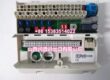
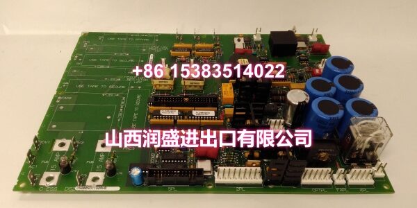
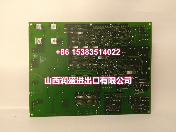
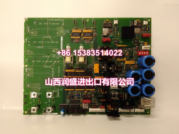
GE DS200SDCIG2AHB is a DC power and instrumentation board for the GE Speedtronic Mark V control system family. It is used as an interface board in GE DC2000-type drive systems, providing regulated power distribution and instrumentation support for associated drive control circuitry.
The board is documented with multiple power output rails, including +5 VDC at 4 A, ±15 VDC at 0.4 A, +24 VDC, and 115 VAC at 0.4 A. These outputs supply auxiliary power to drive control circuits, instrumentation circuits, and related I/O boards within the drive cabinet.
Power circuits are protected by fuses FU1–FU3, FU5, and FU6, with associated LED indicators that illuminate when a fuse has opened. The board uses Berg-type or manually removable jumpers, identified by the JP nomenclature, for factory test purposes and customer-selectable options.
The replacement procedure is covered in GE manual GEI-100173. Some third-party listings describe this part number with generic power-supply or control parameters that are not confirmed by GE documentation; those values should not be treated as authoritative without verification against the physical board label and GE manuals.
Key Technical Specifications
| Parameter | Value |
|---|---|
| Manufacturer | GE (GE Energy / GE Digital / GE Industrial Systems) |
| Part Number | |
| Product Type | DC Power & Instrumentation Board (SDCI) |
| Series | GE Speedtronic Mark V / DS200 |
| Typical Application | DC2000-type drive interface, power distribution, instrumentation support |
| Power Outputs | +5 VDC (4 A); ±15 VDC (0.4 A); +24 VDC; 115 VAC (0.4 A) |
| Protection | Fuses FU1–FU3, FU5, FU6 with LED indication |
| Jumpers | Berg-type / manually removable (JP nomenclature) |
| Reference Manual | GEI-100173 |
| Status | Legacy / Obsolete |
Note: The SDCI board function, DC2000-type drive interface role, multi-rail power outputs, fuse/LED protection scheme, Berg-type jumpers, and GEI-100173 manual reference are documented for DS200SDCIG2AHB. The exact connector layout, jumper map, LED count, board revision, and cabinet-specific wiring should be verified from the physical board label and GE Mark V documentation.
Quality Control Process (DYNAMIC GENERATION)
- Visual and label inspection. We check the part number, suffix, PCB surface, connectors, jumpers, fuses, LEDs, and mounting hardware for damage or corrosion.
- Fuse and LED inspection. Fuses FU1–FU3, FU5, and FU6 are inspected for correct rating and seating; LED indicators are checked for visible damage.
- Power rail and connector check. Power connectors and terminal points are verified for correct pin continuity and no short circuits.
- Jumper and configuration check. JP jumpers are recorded and compared against the original board or system documentation.
- Final packaging. After passing inspection, the board is anti-static bagged and foam-packed for shipment.
Replacement Pitfall Guide (DYNAMIC GENERATION)
❗ Confirm the SDCI function before installation. DS200SDCIG2AHB is a DC power and instrumentation board for DC2000-type drives; do not confuse it with SDCC drive control boards or analog I/O boards.
❗ Label all connectors before removal. The board distributes multiple power rails; miswiring can damage downstream control or instrumentation circuits.
❗ Record fuse and LED status before removal. Document which LEDs are lit and which fuses are intact for troubleshooting reference.
❗ Copy jumper settings from the original board. JP jumpers may affect factory test mode or customer options; do not change them without verification.
❗ Verify power rail voltages after installation. Confirm +5 VDC, ±15 VDC, +24 VDC, and 115 VAC outputs match system requirements before energizing downstream boards.
❗ Observe live-voltage safety. The board carries multiple power rails; disconnect drive power and verify zero energy before handling.
❗ Handle as ESD-sensitive equipment. Always use anti-static wrist straps and handling procedures during removal, installation, and storage.
Keep these in mind and you’ll cut 90% of rework time.
Compatibility Matrix & Benchmarks
| Original Model | Replacement / Successor Model | Compatibility Level | Migration Notes |
|---|---|---|---|
| GE | GE | Direct | Same part number; verify connector layout, jumper map, and fuse ratings. |
| GE | GE DS200SDCI variants | Needs Adaptation | Same SDCI family; suffix differences may affect revision or configuration. |
| GE | GE DS200SDCC variants | Not Compatible | SDCC is a drive control board, not a power/instrumentation board. |
| GE | GE DS200CDBA variants | Not Compatible | CDBA is a contactor driver board; different function and wiring. |
| GE | Mark VIe / IS200/IS220 modules | Not Compatible | Different platform and architecture; not a direct replacement. |
Benchmark highlights
- GE Speedtronic Mark V SDCI DC power and instrumentation board.
- Used as an interface board in GE DC2000-type drive systems.
- Provides +5 VDC, ±15 VDC, +24 VDC, and 115 VAC power outputs.
- Fuse-protected power circuits with LED fault indication.
- Berg-type jumpers for factory test and customer options.
- Replacement procedure referenced in GE manual GEI-100173.
- Legacy product; best suited for existing Mark V drive system maintenance and like-for-like replacement.