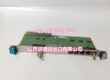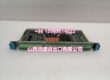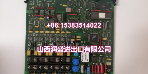
Product Core Brief
- Model: AS111-1
- Brand: ALSTOM
- Series: Alspa CE2000 / AS111 Analog I/O Series
- Core Function: Converts control-system digital values into stable analog outputs for actuators, valves, drives, and process regulators.
- Product Type: Analog Output Module
- Key Specs: 8-channel analog output | 0–20 mA / 4–20 mA | 24 V DC supply | Isolated analog/digital circuits
- Condition: New Original / New Surplus
Product Introduction
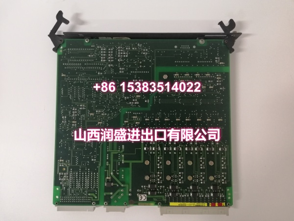
ALSTOM AS111-1 is an analog output module used in ALSTOM Alspa CE2000 and related industrial control platforms. It converts digital control values into precise current outputs for field devices such as control valves, actuators, VFD speed references, and process regulators.
The module typically provides 8 analog output channels with 0–20 mA or 4–20 mA current signals, 24 V DC supply, and isolation between analog and digital circuits to reduce noise in industrial cabinets. It is commonly applied in power generation, turbine control, oil & gas, chemical processing, water treatment, and general process automation.
Exact output type, scaling, firmware, and terminal assignment should be confirmed from the installed nameplate and I/O database before commissioning.
Key Technical Specifications
| Parameter | Value |
|---|---|
| Full Model | M |
| Product Type | Analog Output Module |
| System Platform | Alspa CE2000 / ALSTOM DCS & Automation Platform |
| Output Channels | 8 channels |
| Output Signal | 0–20 mA / 4–20 mA current |
| Supply Voltage | 24 V DC (approx. 19.2–30 V) |
| Isolation | Analog/digital circuit isolation |
| Diagnostics | Loop self-check and module status indication |
| Typical Accuracy | Industrial-grade process control accuracy |
| Form Factor | Rack-mount / slot-in I/O module |
| Installation | Backplane or I/O rack mounting |
Quality Control Process
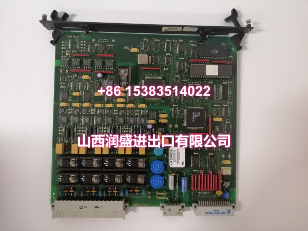
- Visual and revision check: Inspect PCB, terminal block, edge connector, and AS111-1 labeling for consistency with site documentation.
- Power and isolation check: Verify 24 V DC supply rails and analog/digital isolation before connecting field loops.
- Channel output test: Source 4–20 mA on each channel and verify current accuracy with a calibrated loop calibrator or Fluke multimeter.
- Scaling and diagnostics check: Confirm zero/span scaling, fault indication, and open-loop detection where supported.
- Final packing: Record test results, apply asset labels, and ship in anti-static packaging with terminal and connector protection.
Replacement Pitfall Guide
❗ Confis . Some spare lists mix base and revision codes; channel count and terminal mapping may differ.
❗ Don’t assume 0–10 V output. Public references describe AS111-1 primarily as a 4–20 mA / 0–20 mA current output module; voltage output must be verified on the nameplate.
❗ Check loop power and load resistance. Incorrect loop supply or excessive load can cause output saturation or calibration drift.
❗ Verify I/O scaling after replacement. A physically matching module may still need range, zero/span, and tag mapping updates in the control database.
Keep these in mind and you’ll cut 90% of rework time.
Compatibility Matrix & Benchmarks
| Original Model | Replacement / Successor Model | Compatibility Level | Migration Notes |
|---|---|---|---|
| M | M | Direct | Like-for-like replacement when channel count, scaling, and terminal mapping match. |
| M | ALSTOM AS111-series AO module | Needs Adaptation | Confirm channel count, current/voltage type, and I/O address mapping. |
| M | Alspa CE2000 successor AO card | Needs Adaptation | Verify backplane compatibility, scaling, and control program configuration. |
- Typical use: Analog output for valve positioners, actuators, VFD references, and process control loops.
- Key verification points: 4–20 mA output, 8-channel configuration, 24 V DC supply, loop isolation, and I/O scaling.