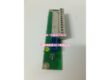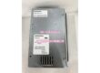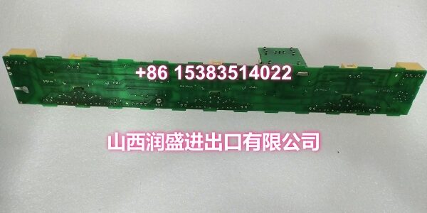
Product Core Brief
- Model: DSMB-02C
- Brand: ABB
- Order Code: 3AFE64666606
- Series: ACS800 Multi-Drive Series
- Core Function: Rectifier unit control board for ABB ACS800 multi-drive systems, managing rectifier operation, gate control, and drive protection.
- Product Type: Rectifier Control Board / Drive Control Board
- Key Specs: ACS800 Multi-Drive Compatible | Rectifier Unit Control | Gate Pulse Generation | Drive Protection & Diagnostics | Plug-in PCB Module
- Note: Condition: New Original (New Surplus). Origin: Switzerland / Finland.
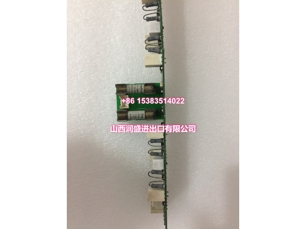
Key Technical Specifications
| Parameter | Value |
|---|---|
| Manufacturer Part Number | 3AFE64666606 |
| Device Model | |
| Device Type | Rectifier Control Board / Drive Control Board |
| Series | ACS800 Multi-Drive Series |
| Function | Rectifier unit control and monitoring |
| Compatible Drives | ACS800-704, ACS800 Multi-Drive rectifier units |
| Power Supply | 24VDC (logic circuits) |
| Mounting | Plug-in PCB module (card slot) |
| Connector Type | Edge connector, terminal block |
| Operating Temperature | 0°C to +60°C |
| Storage Temperature | -40°C to +85°C |
| Humidity Range | 5% to 95% RH, non-condensing |
| IP Rating | Not rated (indoor use in control panel) |
| Dimensions | Approx. 160mm x 100mm x 20mm |
| Weight | Approx. 120g |
| Typical Applications | Rectifier unit control, multi-drive systems, industrial drive applications |
| Origin | Switzerland / Finland |
| Condition | New Original (New Surplus) |
Product Introduction
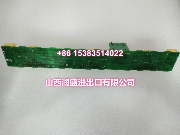
The ABB DSMB-02C (order code 3AFE64666606) is a rectifier unit control board designed for ABB’s ACS800 multi-drive series. It serves as a critical control component for rectifier units, managing gate pulse generation, drive protection, and system monitoring to ensure reliable rectifier operation in industrial drive applications.
In industrial drive systems where rectifier reliability directly impacts production uptime, the DSMB-02C delivers precise control of the rectifier unit’s switching operations. The board handles gate pulse generation for the rectifier’s thyristors or IGBTs, monitors DC bus voltage and current, and provides comprehensive drive protection including overvoltage, undervoltage, overcurrent, and overtemperature protection. Its diagnostic capabilities report fault codes and status information to the drive’s main control unit, enabling rapid troubleshooting during maintenance.
The DSMB-02C is specifically designed for the ACS800 multi-drive rectifier unit architecture, where a single common DC bus supplies power to multiple inverter modules. In this configuration, the rectifier control board coordinates the rectifier’s operation to maintain stable DC bus voltage under varying load conditions from the connected inverters. This multi-drive architecture is commonly used in applications such as paper machines, conveyor systems, and test benches where multiple motors need to be driven from a single power source.
The board features a plug-in PCB module design with edge connectors and terminal blocks for field wiring connections. Its compact form factor (approximately 160mm x 100mm x 20mm) allows it to be installed directly into the rectifier unit’s control slot, minimizing wiring complexity and reducing installation time. The module operates on 24VDC logic power and is rated for industrial ambient temperatures from 0°C to +60°C.
For maintenance teams supporting ACS800 multi-drive installations, the DSMB-02C is a direct drop-in replacement for failed or degraded rectifier control boards. Its standardized form factor and connector layout ensure compatibility with existing rectifier unit configurations, avoiding the need for mechanical modifications or rewiring. When replacing a DSMB-02C, always verify that the order code (3AFE64666606) matches the original board to ensure full compatibility with the drive’s firmware and hardware configuration.
QA & Testing SOP
Every unit goes through a structured verification process before shipment:
- Visual Inspection: Check the PCB for cracks, burnt components, corrosion on connector pins, and physical damage to the board. Verify that all surface-mount and through-hole components are securely soldered with no cold joints or solder bridges.
- Connector Pin Verification: Inspect the edge connector pins for straightness, corrosion, or bending. Bent pins cause poor contact with the rectifier unit’s backplane connector, leading to intermittent communication failures or complete board malfunction.
- Power-On Self-Test: Apply 24VDC logic power and verify that the board’s status indicators (if present) show normal operation. Check for any abnormal heating of components during the initial power-on.
- Gate Pulse Output Test: Where test infrastructure allows, verify that the board generates correct gate pulse signals for the rectifier’s switching devices. Measure pulse timing, amplitude, and phase relationships to ensure they meet ACS800 specifications.
- Protection Circuit Verification: Test the board’s protection functions including overvoltage, undervoltage, overcurrent, and overtemperature detection. Verify that the board correctly reports fault conditions and shuts down gate outputs when protection thresholds are exceeded.
- Anti-Counterfeit & Packaging: Verify authenticity markings on the PCB and components. Each unit is shipped in anti-static protective packaging with desiccant to prevent moisture absorption and connector oxidation during transit.
smart
Installation Pitfalls & Guide
Installing or replacing a rectifier control board requires careful attention to safety procedures and proper handling.
❗ Power-Down and Discharge Before Installation: Always disconnect all AC and DC power to the drive system before removing or inserting the DSMB-02C board. Wait for the DC bus capacitors to fully discharge (verify with a multimeter that DC bus voltage is below 5V) before touching any internal components. Residual DC bus voltage can cause severe electric shock or damage to the replacement board.
❗ Anti-Static Protection: Always wear an anti-static wrist strap when handling the DSMB-02C board. The PCB contains sensitive electronic components that can be damaged by electrostatic discharge (ESD). Handle the board by its edges only, avoiding contact with components or connector pins.
❗ Correct Board Orientation: The DSMB-02C must be inserted into the rectifier unit’s control slot with the correct orientation. Forcing the board into the wrong orientation can damage the edge connector pins and the backplane connector. Align the board’s connector with the slot guides and push firmly and evenly until fully seated.
❗ Firmware and Hardware Version Matching: Verify that the replacement DSMB-02C’s hardware version and firmware are compatible with the existing ACS800 drive system. Mismatched versions can cause communication errors, incorrect gate pulse timing, or drive faults. Check the drive’s nameplate and configuration documentation before ordering a replacement.
❗ Wiring Verification: Before reconnecting field wiring to the replacement board, verify that each wire is correctly labeled and corresponds to the documented terminal assignments. Incorrect wiring can cause drive faults, protection trips, or damage to the board or connected equipment.
4-Step Replacement Guide:
- Pre-install: Document the existing drive configuration, including drive type, power rating, firmware version, and any custom parameters. Back up the drive’s parameter set. Verify the replacement board’s order code (3AFE64666606) matches the original. Prepare anti-static protection, tools, and a multimeter for DC bus voltage verification.
- Removal: Disconnect all AC and DC power to the drive system. Wait for DC bus capacitors to fully discharge and verify with a multimeter. Wear an anti-static wrist strap. Disconnect all wiring from the board’s terminal blocks and label each wire. Loosen the board’s retention screws or clips. Gently pull the board straight out of the control slot. Inspect the backplane connector for damage.
- Install: Align the new DSMB-02C’s edge connector with the control slot guides. Push firmly and evenly until fully seated. Secure the board with retention screws or clips. Reconnect all wiring to the correct terminals according to the documented assignments. Verify that all connections are secure and properly torqued.
- Power-on Test: Apply 24VDC logic power first and verify that the board powers up without faults. Then apply main AC power to the drive system. Enter the drive’s parameter menu and verify that the rectifier control board is recognized with no fault codes. Run the drive at low speed and monitor for any abnormal behavior. Gradually increase speed and load while monitoring DC bus voltage, current, and temperature readings.
Technical FAQ
1. What is the difference between DSMB-01C and DSMB-02C? Both are control boards for ABB ACS800 drives, but they serve different functions. The DSMB-01C is typically used as a main control board or power board for certain ACS800 configurations, while the DSMB-02C is specifically designed as a rectifier unit control board for the ACS800 multi-drive series. They are not interchangeable. Always verify the exact board type and order code before ordering a replacement.
2. Can the DSMB-02C be used with ACS800 single drives? The DSMB-02C is designed for the ACS800 multi-drive series rectifier units. It is not typically used with ACS800 single drives, which have different control board configurations. Verify your drive’s type (single drive vs. multi-drive rectifier unit) and consult the drive’s documentation before ordering a replacement board.
3. What are common fault symptoms of a failing DSMB-02C? Common symptoms include rectifier unit not starting, DC bus voltage instability, gate pulse errors, overvoltage or undervoltage faults without actual voltage issues, communication errors between the rectifier and inverter units, and intermittent drive trips. If you’re experiencing any of these symptoms, check the drive’s fault log for specific error codes that may point to the rectifier control board.
4. How do I verify that the replacement DSMB-02C is compatible with my ACS800 drive? Check the following: (1) The order code on the replacement board (3AFE64666606) matches the original. (2) The hardware version is the same or a documented compatible revision. (3) The drive’s firmware version supports the replacement board. (4) The physical connector layout and mounting dimensions match the original. When in doubt, provide the drive’s nameplate information and the original board’s serial number to the supplier for compatibility verification.
5. What’s the difference between New Surplus and Refurbished for rectifier control boards? We supply this unit as New Original (New Surplus)—unused, original factory stock. This comes with a standard 12-month warranty. Refurbished rectifier control boards carry risks including