Product Core Brief
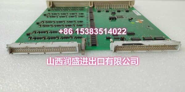
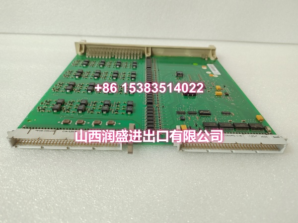
- Model: DSDX404
- Brand: ABB
- Series: ABB 800xA / Legacy DCS Control Systems
- Core Function: Digital input/output basic unit that collects discrete ON/OFF signals from field devices (limit switches, proximity sensors, relay contacts, push buttons) and outputs control signals to field actuators (solenoid valves, relays, indicator lights), serving as the interface between the ABB controller and field equipment.
- Product Type: Digital Input/Output Module / Digital I/O Board
- Key Specs: Multi-channel digital I/O | 24VDC operating voltage | Modular plug-in design | Compatible with ABB 800xA chassis | High reliability with EMC certification
- Condition: New Original / New Surplus
Key Technical Specifications
- Product Type: Digital Input/Output Basic Unit for DCS/PLC Systems
- Brand: ABB
- Model Number:
- Series: ABB 800xA / Legacy DCS Control Systems
- Core Function: Digital I/O interface — collects discrete ON/OFF status signals from field devices (limit switches, proximity sensors, relay contacts, push buttons, emergency stop buttons) and transmits them to the ABB controller for process monitoring and interlock logic; simultaneously outputs control signals from the controller to field actuators (solenoid valves, relays, indicator lights, motor starters) for equipment control
- Input Signal Type: Digital/discrete signals from field devices — typically 24VDC dry contact or transistor output signals conforming to EN 61131-2 Type 1 standard
- Output Signal Type: Digital/discrete control signals to field actuators — typically 24VDC transistor or relay output
- Operating Voltage: 24V DC (power supplied from backplane)
- Mounting Method: Modular plug-in format for installation in compatible ABB 800xA DCS/PLC chassis — drop-in replacement with minimal downtime
- Physical Dimensions: Approximately 350mm (depth) × 255mm (width) × 20mm (height), net weight approximately 0.44kg
- Operating Environment: Control room installation; operating temperature -20°C to +60°C, humidity 5–95% non-condensing, meeting industrial G3 corrosion resistance standards
- Environmental Rating: IP20 protection rating, suitable for indoor industrial control room environments
- Origin: Switzerland
- Compatibility: ABB 800xA series and legacy DCS/PLC control systems — serves as a dedicated digital I/O interface for applications requiring discrete signal acquisition and control output
- Typical Applications: Valve position feedback and control in chemical, power, and oil & gas plants; equipment run/stop/fault status monitoring on production lines; emergency stop and safety interlock signal acquisition; motor start/stop control and status indication; serving as a critical spare part for lifecycle support of mature ABB DCS/PLC installations where digital I/O functionality is required
Product Introduction
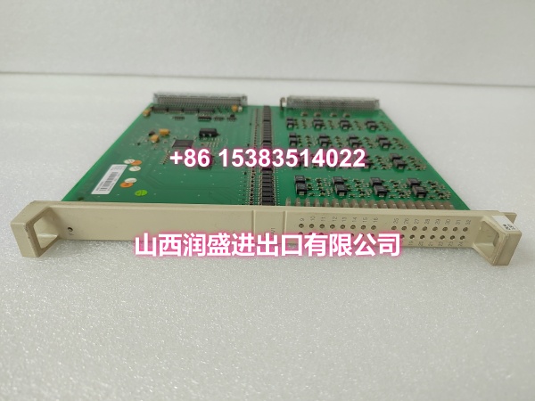
The ABB DSDX404 is a digital input/output basic unit from ABB’s 800xA / legacy DCS control systems, engineered to provide reliable discrete signal acquisition and control output in industrial automation installations. As a dedicated digital I/O interface in ABB controller architectures, the DSDX404 is responsible for collecting ON/OFF status signals from field devices — limit switches confirming equipment position, proximity sensors detecting material presence, relay contacts signaling equipment status, or push buttons for operator input — and transmitting these signals to the ABB controller for process monitoring, interlock logic, and safety functions. Simultaneously, it outputs control signals from the controller to field actuators such as solenoid valves, relays, and indicator lights, enabling the controller to directly influence the physical process.
What makes the DSDX404 essential in ABB installations is its role as the fundamental bridge between the controller’s digital logic and the physical world of switches and actuators. Unlike specialized modules (counter boards, analog I/O), the DSDX404 handles the most common type of industrial signal — the simple ON/OFF state — but does so with the reliability and diagnostic capability required in critical process applications. The module’s design supports multiple channels of digital I/O, allowing a single module to monitor and control numerous field devices, reducing the number of module slots required in the chassis and simplifying wiring.
For system integrators and MRO procurement teams maintaining ABB 800xA or legacy DCS/PLC systems, the DSDX404 is a foundational spare part that becomes critical when any discrete signal acquisition or control output function is part of the process. A failed digital I/O module can result in loss of valve position feedback, inability to start/stop equipment, loss of safety interlock signals, or false alarms — all of which can lead to production downtime, safety incidents, or equipment damage. The DSDX404’s modular plug-in design means replacement is a straightforward swap with no rewiring typically required at the module level, allowing maintenance teams to restore I/O functionality quickly during a maintenance window.
As plants extend the lifecycle of mature ABB installations, having verified genuine DSDX404 modules on hand ensures continuity of critical monitoring and control functions and reduces the risk of production disruptions caused by digital I/O board failures.
QA & Testing SOP
Every unit undergoes a standardized verification process before shipment:
- Visual & Anti-Counterfeit Check: Inspect the module housing for proper ABB branding and part number marking (DSDX404). Check for physical damage including cracked PCB, damaged connector pins, burnt components, or signs of moisture ingress (corrosion, white residue on contacts).
- Connector Pin Inspection: Examine the backplane connector pins and field wiring connectors for straightness, corrosion, or bending. Bent pins can cause intermittent connections or short circuits when inserted into the DCS/PLC chassis.
- Backplane Power Test: Insert the module into a test ABB 800xA chassis and verify that it correctly draws 24VDC power from the backplane with no abnormal current draw or voltage drop.
- Digital Input Test: Apply known ON/OFF signals to each digital input channel and verify that the module correctly reports the input state to the test controller with no false readings or missed states.
- Digital Output Test: Command each digital output channel to ON and OFF states from the test controller and verify that the module correctly outputs the corresponding voltage level at each output terminal.
- Channel Isolation Test: Verify that each input/output channel is properly isolated from adjacent channels and from the backplane, preventing cross-talk or ground loop issues.
- Controller Communication Test: Verify that the module correctly reports all I/O status data to the test controller and that the controller can read/write I/O values without communication errors.
- Long-Duration Stability Test: Run the module under continuous I/O cycling for an extended period to verify stable operation with no channel failures, communication dropouts, or thermal issues.
- Anti-Static & Mechanical Protection: After passing all tests, the module is placed in anti-static shielding with protective caps on connectors. It is then packed in rigid cardboard with foam cushioning to prevent mechanical shock and ESD damage during transit.
Installation Pitfalls & Guide
Real-World Risks When Replacing This Module:
❗ Input/Output Wiring Confusion: The DSDX404 combines both digital input and digital output channels on the same module. Confusing input terminals with output terminals during reconnection can cause damage to the module or field devices. Always verify wiring against the I/O documentation and terminal assignment diagram before applying power.
❗ Signal Voltage Level Mismatch: The DSDX404 expects digital signals at a specific voltage level (typically 24VDC). If field devices operate at a different voltage level, a signal converter or interface relay may be required. A mismatch can cause false readings or damage to the input/output circuits.
❗ Incorrect Slot Placement: The DSDX404 must be installed in the designated slot position specified in the system configuration. Installing it in the wrong slot can cause the controller to fail to recognize the I/O module, resulting in complete loss of I/O functionality. Always verify the slot assignment matches the system documentation before insertion.
❗ Loss of I/O State on Replacement: When replacing a failed DSDX404, all output states will be lost and all input readings will be unavailable during the swap. For critical control outputs (e.g., safety interlocks, emergency systems), always schedule the replacement during a planned maintenance window and bypass or hold the process if possible.
❗ Hot-Swap Risk: While some ABB DCS/PLC chassis support hot-swapping of I/O modules, removing or inserting the DSDX404 while the system is powered can cause momentary loss of I/O — potentially triggering false alarms or unintended equipment actions. For applications where I/O continuity is critical, always schedule the replacement during a planned maintenance window.
❗ Configuration Mismatch: If the DSDX404 has been configured with specific channel assignments, filtering parameters, or diagnostic settings, ensure that the replacement module is configured identically. A configuration mismatch can cause unexpected behavior such as incorrect input readings or wrong output states.
4-Step Replacement Guide:
- Pre-Install: Identify the failed module slot and document the existing configuration (slot position, I/O channel assignments, wiring connections, current output states from the controller/SCADA). Back up the current controller configuration including any I/O-specific settings. If possible, schedule the replacement during a planned maintenance window and notify operations of potential loss of I/O functionality.
- Removal: If hot-swap is supported per the system documentation, follow the proper hot-swap procedure. Otherwise, power down the DCS/PLC chassis. Disconnect all field wiring cables from the module, labeling each cable for reconnection. Release the module locking mechanism and carefully slide the old DSDX404 out of the chassis slot. Inspect the backplane connector for damage or debris.
- Install: Insert the new DSDX404 module into the correct chassis slot, ensuring proper alignment with the backplane connector. Secure the module with the locking mechanism. Reconnect all field wiring cables to the correct terminals, verifying input vs. output assignments and signal polarity. Double-check that wiring matches the I/O documentation.
- Power-On Test: Power up the chassis (if it was shut down). Verify that the module powers up correctly from the backplane. Check the controller for any I/O fault codes related to the digital I/O module. Apply test signals to input channels and verify that the module correctly reports input states to the controller. Command output channels to ON/OFF states and verify correct output at the terminals. Verify that any configured parameters (filtering, diagnostics) function correctly. Monitor the system for stable operation before returning to full production.
Technical FAQ
What is the difference between the DSDX404 and a dedicated DI or DO module? The DSDX404 is a combined digital input/output basic unit that provides both input and output channels on a single module, while dedicated DI modules (like DSDI110) or DO modules (like DSDO110) provide only input or only output channels. The DSDX404 is suitable for applications that require a mix of input and output signals in a compact footprint, reducing the number of module slots required. For applications requiring a large number of only inputs or only outputs, dedicated single-function modules may be more appropriate.
What types of field devices can connect to the DSDX404? The DSDX404 is designed to connect to standard industrial digital devices. Input side: limit switches, proximity sensors, push buttons, relay contacts, emergency stop buttons, and other discrete signal sources. Output side: solenoid valves, relays, indicator lights, motor starters, and other discrete actuators. The field devices must be compatible with the module’s voltage and current specifications.
What are common failure modes for this module? Common failure modes include: backplane connector pin damage from repeated insertion/removal; input circuit damage from voltage transients on field wiring (especially if external surge protection is not installed); output circuit damage from short circuits or overcurrent on actuator wiring; PCB trace corrosion from moisture ingress in humid environments; and communication failure preventing the controller from reading/writing I/O values. In most cases, a failing DSDX404 will report incorrect input states, fail to switch outputs, or stop communicating entirely, which the controller will flag as an I/O fault.
Is the DSDX404 compatible with ABB 800xA systems? Yes, the DSDX404 is designed for ABB 800xA series and legacy DCS/PLC control systems. It serves as a digital input/output basic unit in these architectures. Always verify compatibility with your specific controller model and firmware version before ordering.
What warranty do you offer on New Surplus parts? We provide a full 12-month warranty on all New Original / New Surplus units. This is fundamentally different from refurbished or pulled modules, which often carry 30–90 day warranties and come with unknown operational history, potential connector wear, and degraded I/O accuracy. For a digital I/O module used in safety interlocks or critical process control, the reliability difference between new surplus and refurbished directly impacts process safety and the risk of false trips or missed alarms.