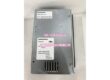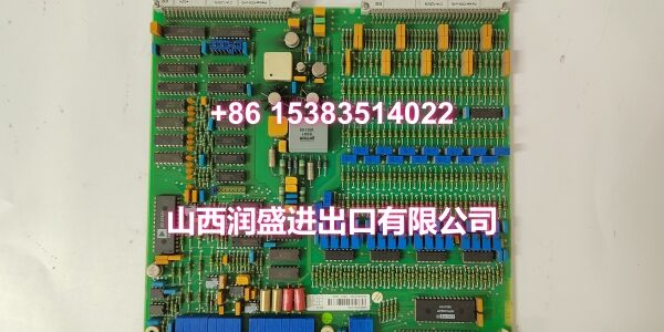
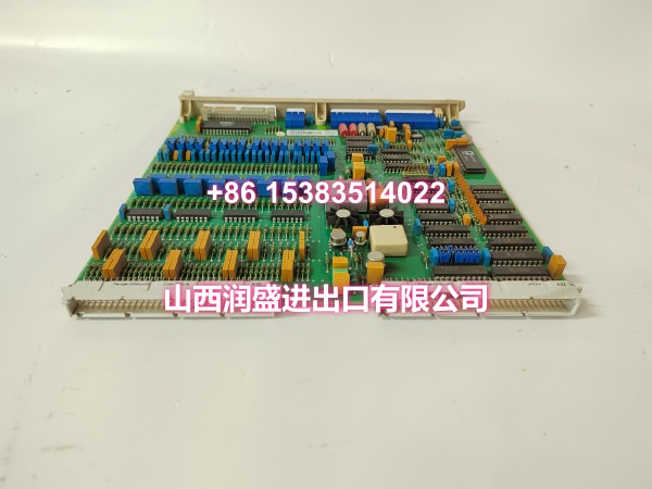
Product Core Brief
- Model: DSAO110
- Brand: ABB
- Series: ABB DCS (Distributed Control System) Product Family
- Core Function: High-precision analog output module that converts digital control signals into standard analog signals (4-20mA/0-10V) for precise actuator control in industrial automation systems.
- Product Type: Analog Output Module / DCS I/O Card
- Key Specs: 4 independent analog output channels | 16-bit resolution | ±0.1% full-scale accuracy | 4-20mA/0-10V output | Compatible with control valves, VFDs, servo drives
- Condition: New Original / New Surplus
Key Technical Specifications
- Product Type: Analog Output Module for DCS Systems
- Brand: ABB
- Model Number:
- Order Code: 57120001-AT
- Series: ABB DCS Product Family
- Output Channels: 4 independent analog output channels
- Output Signal Types: 4-20mA DC current signal and 0-10V DC voltage signal — industry-standard signals compatible with virtually all industrial actuators
- Output Accuracy: ±0.1% of full scale — ensures output analog signals precisely reflect control system instructions
- Resolution: 16-bit — enables fine-grained output signal adjustment for precise actuator positioning and speed control
- Response Time: Fast response to digital input signals, suitable for real-time control applications requiring accurate and reliable operation
- Communication: Interfaces with the DCS system via the module bus; supports remote communication for data exchange with other devices and systems, enabling flexible integration into distributed control architectures
- Operating Voltage: 24V DC (supplied from the DCS system backplane)
- Mounting Method: Standard modular plug-in design — one independent installation unit per module, easy to install and replace without complex wiring operations
- Environmental Rating: Designed for industrial environments with good anti-interference capability and long-term stability
- Typical Applications: Control valve positioning in process plants (flow, pressure, level control loops); VFD speed reference signals for pump and fan control; servo drive command signals for precision motion control; damper and actuator positioning in HVAC and power generation systems; analog signal output for batch process control in food, pharmaceutical, and chemical manufacturing; test bench and pilot plant analog signal generation
Product Introduction
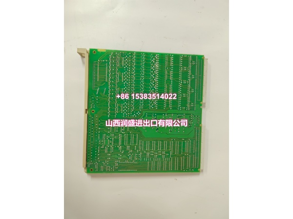
The ABB DSAO110 57120001-AT is a 4-channel analog output module from ABB’s DCS product family, engineered for industrial automation applications where analog signal accuracy and stability are critical. As the bridge between the digital control system and field execution equipment, the DSAO110 converts the controller’s digital output commands into precise 4-20mA or 0-10V analog signals that drive control valves, variable frequency drives, servo motors, and other analog actuators.
What sets the DSAO110 apart in the DCS I/O landscape is its combination of 16-bit resolution and ±0.1% full-scale accuracy. In process control loops — particularly in flow, pressure, and level control — even small output signal errors can cascade into significant process deviations. A control valve receiving a 12.00mA signal instead of the intended 12.02mA may be slightly off-position, causing flow imbalance that affects downstream unit operations. The DSAO110’s high resolution and accuracy ensure that the controller’s digital command is faithfully reproduced at the field device, minimizing loop error and improving overall process stability.
The 4-channel configuration strikes a practical balance between channel density and application flexibility. Unlike high-density 8- or 16-channel analog output modules that may be overkill for smaller control loops, the DSAO110’s 4 channels are well-suited for typical control valve clusters — for example, a reactor system with feed, coolant, reflux, and product outlet valves, or a boiler system with fuel, air, feedwater, and blowdown control valves. Each channel operates independently, allowing mixed signal types (some channels as 4-20mA, others as 0-10V) within the same module to accommodate different actuator requirements.
For system integrators and MRO procurement teams maintaining ABB DCS installations, the DSAO110 is a critical spare part. Analog output modules are among the most failure-prone I/O components in a DCS system — they are constantly driving current into field wiring that may be exposed to moisture, corrosion, induced voltage spikes, and ground loops. When an analog output channel fails, the associated control loop goes to manual or failsafe, potentially disrupting production. Having a verified genuine DSAO110 on hand means you can restore the control loop quickly during a maintenance window without waiting for long-lead OEM orders.
The module’s programmability is another practical advantage. Through the DCS engineering tool, each channel can be configured for the required signal type (4-20mA or 0-10V), output range scaling, fail-safe output value (on communication loss or controller failure), and diagnostic alarm thresholds. This flexibility allows the same hardware platform to serve diverse applications without requiring different module types for different signal standards.
QA & Testing SOP
Every unit undergoes a standardized verification process before shipment:
- Visual & Anti-Counterfeit Check: Inspect the module housing for proper ABB branding and part number marking (DSAO110, 57120001-AT). Check for physical damage including cracked PCB, damaged connector pins, burnt components, or signs of moisture ingress (corrosion, white residue on contacts).
- Connector Pin Inspection: Examine the backplane connector pins and field wiring terminal block for straightness, corrosion, or bending. Bent pins can cause intermittent connections or short circuits when inserted into the DCS chassis.
- Channel Continuity Test: Verify electrical continuity on all 4 output channels to confirm no open circuits or short circuits exist in the output stage.
- Output Accuracy Test (4-20mA): Command each channel to output specific current values (4mA, 8mA, 12mA, 16mA, 20mA) and measure the actual output with a precision ammeter. Verify that the error is within ±0.1% of full scale (±20μA for a 20mA span).
- Output Accuracy Test (0-10V): Command each channel to output specific voltage values (0V, 2.5V, 5V, 7.5V, 10V) and measure the actual output with a precision voltmeter. Verify that the error is within ±0.1% of full scale (±10mV for a 10V span).
- Resolution Test: Command small incremental changes in output (e.g., 1 LSB step at 16-bit resolution) and verify that the output changes smoothly without jumps or dead zones, confirming the full 16-bit resolution is functional.
- Fail-Safe Output Test: Simulate a communication loss or controller failure condition and verify that each channel outputs the configured fail-safe value (e.g., 0mA, 4mA, or last known value) as programmed in the DCS configuration.
- Backplane Communication Test: Insert the module into a test DCS chassis and verify that the controller recognizes the module, can write output values to all 4 channels, and reports no fault codes.
- Anti-Static & Mechanical Protection: After passing all tests, the module is placed in anti-static shielding with protective caps on connectors. It is then packed in rigid cardboard with foam cushioning to prevent mechanical shock and ESD damage during transit.
Installation Pitfalls & Guide
Real-World Risks When Replacing This Module:
❗ Incorrect Signal Type Configuration: The DSAO110 supports both 4-20mA and 0-10V output. If the DCS configuration does not match the physical wiring (e.g., the module is configured for 4-20mA but wired to a 0-10V actuator), the actuator will receive the wrong signal level and operate incorrectly. Before installation, verify the signal type configuration in the DCS engineering tool matches the field device requirements.
❗ Ground Loop Issues: Analog output signals are susceptible to ground loops when the DCS chassis ground and the field device ground are at different potentials. This can introduce noise into the analog signal, causing actuator hunting or instability. If ground loops are suspected, use isolated analog output modules or install signal isolators in the field wiring.
❗ Wiring Polarity Reversal: For 4-20mA current loops, reversing the positive and negative wiring will prevent the actuator from receiving the correct signal. Always verify wiring polarity against the terminal diagram before energizing the loop. For 0-10V outputs, ensure the signal and common connections are correct.
❗ Slot Addressing Conflict: In the DCS system, each module slot has a fixed address. Installing the DSAO110 in the wrong slot can cause the controller to misidentify the module type, leading to incorrect data mapping or system faults. Always verify the slot assignment matches the system configuration before inserting the module.
❗ Hot-Swap Risk: While some DCS modules support hot-swapping, the DSAO110 may not. Removing or inserting the module while the system is powered can cause transient output signals that may drive actuators to unexpected positions — potentially dangerous in critical control loops (e.g., a control valve suddenly opening or closing). Always follow the manufacturer’s hot-swap procedure — if uncertain, power down the chassis or place the affected control loops in manual mode before replacement.
❗ Output Load Mismatch: 4-20mA outputs have a maximum load resistance specification (typically 500-750Ω). If the field wiring resistance plus the actuator input resistance exceeds this limit, the module cannot drive the full 20mA current, resulting in signal clipping at the high end. Verify the total loop resistance is within specification before commissioning.
4-Step Replacement Guide:
- Pre-Install: Identify the failed module slot and document the existing wiring configuration (which terminals connect to which field devices). Back up the current DCS configuration and output scaling parameters from the controller. Place all affected control loops in manual mode to prevent actuator movement during replacement. If possible, schedule the replacement during a planned maintenance window.
- Removal: If hot-swap is supported per the system documentation, follow the proper hot-swap procedure. Otherwise, power down the DCS chassis. Disconnect all field wiring from the module terminal block, labeling each wire pair for reconnection. Release the module locking mechanism and carefully slide the old module out of the chassis slot.
- Install: Insert the new DSAO110 module into the correct chassis slot, ensuring proper alignment with the backplane connector. Secure the module with the locking mechanism. Reconnect all field wiring to the correct terminals, verifying signal type (4-20mA or 0-10V) and polarity for each channel. Double-check that no wires are cross-connected or loose.
- Power-On Test: Power up the chassis (if it was shut down). Verify that the controller recognizes the module and reports no fault codes. Command each channel to output known values (e.g., 4mA, 12mA, 20mA) and measure the actual output at the terminal block with a precision meter. Verify that the field actuators respond correctly to the output signals. Return the control loops to automatic mode and monitor for stable operation.
Technical FAQ
What is the difference between the DSAO110 and a digital output module? The DSAO110 is an analog output module that produces continuously variable signals (4-20mA or 0-10V) for proportional control of actuators like control valves and VFDs. A digital output module produces discrete on/off signals (typically 24V DC) for switching devices like relays, solenoid valves, and motor starters. The DSAO110 is used when you need proportional control (e.g., a valve at 53% open); digital output modules are used when you need simple on/off control (e.g., a pump running or stopped).
Can the DSAO110 output both 4-20mA and 0-10V signals simultaneously? Yes. Each of the 4 channels can be independently configured for either 4-20mA or 0-10V output through the DCS engineering tool. This allows a single DSAO110 module to serve mixed actuator types — for example, channels 1 and 2 driving 4-20mA control valves while channels 3 and 4 drive 0-10V VFD speed references.
What DCS systems is the DSAO110 compatible with? The DSAO110 is part of ABB’s DCS product family and is compatible with ABB DCS system platforms. It interfaces through the DCS module bus and is recognized by the system configuration software. Always verify compatibility with your specific DCS controller model and firmware version before ordering.
What are common failure modes for this module? Common failure modes include: individual channel failures due to overvoltage or short-circuit damage from field wiring; output drift over time causing calibration errors; backplane connector pin damage from repeated insertion/removal; PCB trace corrosion from moisture ingress in humid environments; and firmware/configuration corruption causing the controller to misidentify the module. In most cases, a failed channel will output a fixed value (stuck at 0mA, 20mA, or mid-range) regardless of the controller command.
What warranty do you offer on New Surplus parts? We provide a full 12-month warranty on all New Original / New Surplus units. This is fundamentally different from refurbished or pulled modules, which often carry 30–90 day warranties and come with unknown operational history, potential connector wear, and degraded output accuracy. For an analog output module that directly controls critical process actuators, the reliability difference between new surplus and refurbished directly impacts loop stability and the risk of process upsets.
Need help verifying compatibility with your specific ABB DCS controller or troubleshooting an analog output issue? Share your controller model, system configuration, and the symptoms you’re seeing (e.g., stuck output, inaccurate signal, channel failure), and I can help you diagnose the problem.