
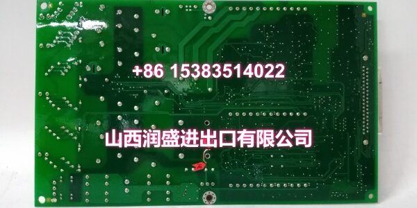
Product Core Brief
- Model: IS200AEPBH1B
- Brand: GE
- Series: Mark V Speedtronic
- Core Function: Scales and conditions analog signals for gas turbine control.
- Product Type: RST Analog I/O Board
- Key Specs: 4-20 mA I/O | LVDT Inputs | Hardware Jumpers
- Condition: New Original / New Surplus
Product Introduction
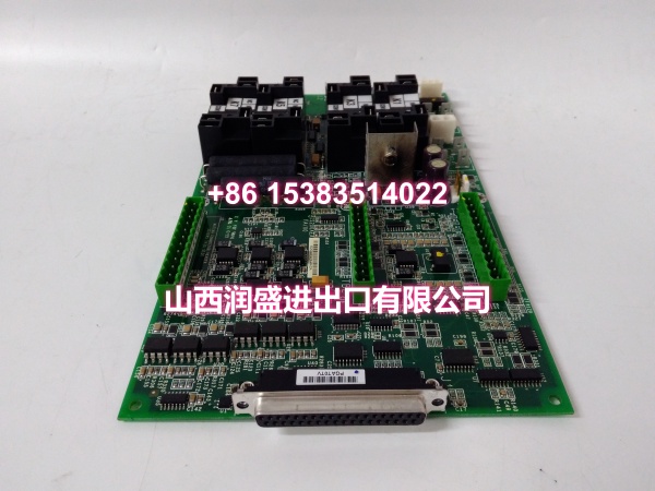
GE is an RST analog I/O board for the Mark V turbine control system. It scales and conditions signals from terminal boards on cores R1, R2, and R3.
This industrial automation unit processes LVDT, thermocouple, and 4-20 mA inputs. Hardware jumpers configure the milliamp output circuits for specific field requirements.
Key Technical Specifications
| Parameter | Value |
|---|---|
| Manufacturer | GE |
| System Platform | Mark V Speedtronic |
| Board Type | RST Analog I/O |
| Signal Types | LVDT, Thermocouple, 4-20mA, Vibration |
| Output Config | Hardware Jumper Selectable |
| Test Port | RS232 via Jumper |
| Data Bus | 3PL Connector to STCA |
| Generator Signals | JE Connector to TCQC |
| Mounting | I/O Core R1, R2, R3 |
| Application | Gas/Steam Turbine Control |
Quality Control Process
Analog conditioning boards require precise calibration checks. We start by inspecting the PCB for cold solder joints or trace corrosion under magnification. Next, the replacement module goes on a test bench. We inject 4-20 mA signals and verify scaling accuracy using a Fluke multimeter. Then, we check the LVDT input conditioning and thermocouple cold-junction compensation with an oscilloscope. Finally, we verify the jumper settings match your configuration and pack it in anti-static shielding.
Replacement Pitfall Guide
❗ Hardware Jumper Settings: This board relies on physical jumpers for configuration. Never assume the new board matches your old settings. Verify every jumper before racking.
❗ 3PL Data Bus Seating: The 3PL connector carries conditioned signals to the STCA board via the COREBUS. A partially seated connector causes intermittent data loss that mimics field sensor failures. Ensure full engagement before tightening.
❗ JE Connector Signals: The JE connector handles generator signals, pulse inputs, and servo valve outputs. Pin damage here affects multiple critical turbine functions. Inspect the connector pins carefully during installation.
Keep these in mind and you’ll cut 90% of rework time.
Compatibility Matrix & Benchmarks
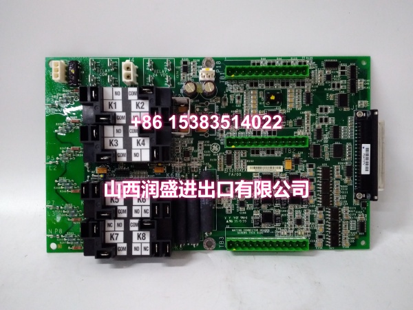
| Original Model | Replacement / Successor Model | Compatibility Level (Direct/Needs Adaptation) | Migration Notes |
|---|---|---|---|
| Direct Drop-In | Verify jumper settings match | ||
| IS200AEPBH1C | Needs Adaptation | Check hardware revision and firmware |
- Signal Processing: Scales 4-20 mA inputs for turbine monitoring
- Data Transfer: 3PL bus to COREBUS for real-time conditioning
Need the hardware jumper configuration chart for this board? I can pull up the jumper settings matrix.




