
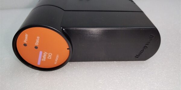
Product Core Brief
- Model: FC-PDIO01
- Brand: Honeywell
- Series: FSC (Fail Safe Controller) / Experion Safety
- Core Function: Processes discrete digital inputs and outputs for safety-critical logic.
- Product Type: Digital Input/Output (I/O) Module
- Key Specs: Digital I/O | Hot-Swappable | SIL Compliant
- Condition: New Original (New Surplus)
Product Introduction
The is a digital I/O module designed for the Honeywell FSC (Fail Safe Controller) system. It serves as a critical interface for reading discrete field signals and driving final control elements within safety-critical loops.
Unlike legacy systems that require a full system shutdown for maintenance, the supports hot-swapping. This allows technicians to safely remove and replace the I/O module directly from the card slot without dropping power, while the controller automatically identifies and configures the new module.
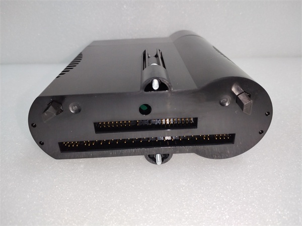
Key Technical Specifications
| Parameter | Value |
|---|---|
| Module Type | Digital Input/Output (I/O) Module |
| System Compatibility | Honeywell FSC / Experion Safety |
| Hot Swap Capability | Supported (No power down required) |
| Auto Configuration | Automatic module recognition |
| Safety Integrity Level | SIL Compliant Architecture |
| Internal Diagnostics | Channel-specific fault detection |
| Bus Interface | FSC System Backplane |
| Mounting | Modular Rack Mount |
| Certifications | IEC 61508 / IEC 61511 |
| Signal Type | Discrete / Digital |
Quality Control Process (Engineer’s Perspective)
We don’t just box these and ship them. Here is our actual bench test workflow.
- Incoming Verification: We verify the serial number against OEM traceability records. A visual inspection checks for bent pins on the backplane connector and ensures the DIN rail clip isn’t cracked.
- Live Functional Test: We mount the unit in a live FSC test rack. We simulate discrete 24 VDC signals on the input channels and force the output channels to verify accurate status bit updates.
- Electrical Parameter Test: We perform a 500 V Megger test between the field wiring terminals and the backplane. Insulation resistance must exceed 10 MΩ. Ground continuity is also verified.
- Firmware Verification: We read the module’s internal firmware revision via the service port. We photograph the DIP switch settings to ensure they match factory defaults before shipping.
- Final QC & Packaging: The module is sealed in an anti-static bag with silica gel. A QC sticker showing the test date and technician initials is applied to the exterior.

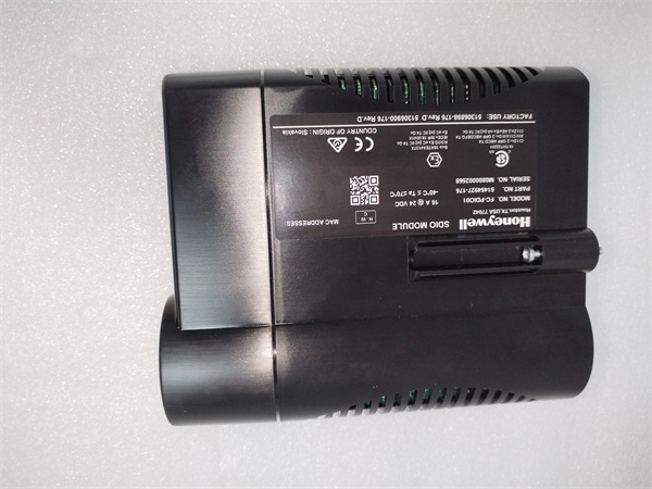
Replacement Pitfall Guide
Field replacements on safety systems are unforgiving. Watch out for these traps.
- Firmware Mismatch: ❗ Critical. A brand-new might have a newer firmware revision than your existing CPU. The FSC controller will block it with a configuration mismatch fault. Always check your system’s allowed firmware matrix before installing.
- DIP Switch / Jumper Misconfiguration: This module uses hardware addressing. If you pull the old card and forget to transfer the binary address switches to the new one, the CPU will report a missing module.
- Terminal / Cable Incompatibility: Inspect the field wiring before plugging in the new card. Ensure all power connections are tight; a loose connection can cause intermittent brownouts that mimic module failure.
- Power Supply Mismatch: Verify your external 24 VDC field power supply has at least 20% headroom over the total calculated load. This module draws current for its own internal monitoring circuits.
- ESD Damage: Safety modules are highly sensitive to electrostatic discharge. Always wear a grounded wrist strap when handling the bare PCB. I’ve seen modules fail bench testing because they were handled on a dry winter day without protection.
Keep these in mind and you’ll cut 90% of rework time.
Compatibility Matrix & Benchmarks
Compatibility
- Honeywell FC- Rev A → FC- Rev B : Direct Replacement — Verify firmware compatibility with CPU.
- Honeywell FC-TDIO01 → FC- : Needs Adaptation — Different I/O architecture; requires logic re-validation.
Benchmarks
- Auto-Config Time: < 500 ms (from module insertion to controller recognition)
- Safe State Transition: < 10 ms (upon critical fault detection)
Need the wiring diagram for the digital I/O termination? I can pull up the termination schematic for the shield grounding and commoning points.




