
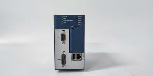
Product Core Brief
- Model: IC695CHS007
- Brand: GE
- Series: PACSystem RX3i
- Core Function: Provides physical mounting, backplane bus communications and power distribution for RX3i CPU, power supply and I/O modules.
- Product Type: 7-Slot Universal Backplane / Baseplate
- Key Specs: 7 physical slots | Dual PCI/Serial bus support | Horizontal mounting only Note: Active production hardware; multiple hardware revisions (-AA, -BA) exist. New original and tested surplus units available globally.
Key Technical Specifications
- Total Slots: 7 slots (Slot 0 = dedicated power supply slot; Slots 1–5 dual bus; Slot 6 PCI-only)
- Bus Architecture: Dual PCI high-speed bus + Serial backplane bus
- Supported Modules: IC695 RX3i modules, select IC694 / IC693 Series 90-30 modules
- External Power Input: 24 VDC terminal block on left side of chassis
- Internal Rail Ratings: 240 mA @3.3 VDC, 600 mA @5 VDC backplane supply
- Operating Temperature: 0°C to 60°C (horizontal mounting only)
- Storage Temperature: -40°C to 85°C
- Mounting: DIN subpanel direct mount; vertical installation voids thermal performance
- Enclosure Requirement: Install inside IP20 / NEMA Type 1 or higher control cabinet
- Dimensions: 264.9 mm × 141.4 mm × 147.3 mm
- Integrated Hardware: Printed slot numbering, chassis ground bar, shield termination points
Product Introduction
This unit acts as the physical and electrical backbone for compact PACSystem RX3i control racks. It routes high-speed PCI communications and distributes regulated backplane power to all plugged-in modules.
The mixed bus slot layout enables gradual migration from legacy Series 90-30 hardware to modern RX3i equipment, reducing overhaul costs for retrofit automation projects.
QA & Testing SOP (Transparency Building)
- Incoming Inspection: Verify part marking and revision suffix. Inspect edge connectors for bent pins, corrosion or cracked PCB traces; check mounting lugs for deformation.
- Live Testing: Populate rack with validated power supply and test modules, apply 24VDC input. Confirm stable backplane voltages and successful module bus handshake over continuous 24-hour cycle.
- Electrical Testing: Use Fluke 115 to monitor 3.3VDC and 5VDC rail stability. Insulation resistance testing must exceed 10MΩ between bus traces and chassis ground.
- Documentation Check: Record hardware revision. Inspect all connector retention latches for proper mechanical engagement.
- Final QC & Packaging: Place unit inside anti-static bag. Attach dated QC test tag before sealed transit packaging.
Installation Pitfalls & Guide (Engineer to Engineer)
❗ Slot Compatibility Restrictions: Slot 6 only accepts PCI-based IC695 modules. Legacy serial-bus IC693/IC694 modules installed here will fail communication. Map hardware slots in PME before assembly. ❗ Mounting Orientation Risk: Vertical mounting disrupts natural convection cooling. Sustained elevated temperatures trigger intermittent module faults and shorten service life. Always install horizontally. ❗ Grounding Errors: Improper chassis grounding creates common-mode noise. Connect the dedicated ground bar to cabinet protective earth; do not rely on DIN rail contact alone. ❗ ESD Dangers: Exposed backplane traces are sensitive to electrostatic discharge. Wear grounded wrist straps during module insertion or rack modification. ❗ Power Budget Miscalculation: Sum 3.3V and 5V current draw of all installed modules. Overloading the power supply creates voltage droop and random CPU fault codes.
Replacement Guide:
- Pre-install: Lockout-tagout main rack power; record slot assignments of every module for PME configuration matching.
- Removal: Extract all modules first; unbolt chassis from subpanel and disconnect 24VDC input wiring and ground cable.
- Install: Secure new chassis horizontally, terminate 24VDC power and protective earth; cross-check ground continuity.
- Power-on Test: Reinstall modules into matching slots, restore power, confirm all modules are recognized in Proficy Machine Edition.
FAQ (Frequently Asked Questions)
Q: Does the backplane support hot swapping of modules? A: Hot-swap capability exists for compatible I/O modules, but the CPU and power supply cannot be hot removed. Hot removal of core controllers will crash the system and risk bus damage.
Q: What is the difference between -AA and -BA? A: These are hardware revision variants. The -BA release includes reinforced PCI connector mechanical improvements. Verify compatibility with your existing CPU before direct replacement.
Q: Can this rack be expanded via serial bus to additional remote racks? A: This baseplate is a main controller rack; it does not support direct expansion cabling. Use dedicated expansion baseplates for distributed I/O layouts.
Q: Can I mix RX3i and Series 90-30 modules in the same rack? A: Yes, within slot rules. Slots 1–5 accept both bus types. Slot 6 rejects legacy serial-only modules. Confirm software configuration matches mixed hardware layout.
Q: What happens if I exceed the backplane current limits? A: Voltage sag occurs on internal power rails. Symptoms include sporadic loss of module recognition, communication timeouts and unexpected CPU faults. Recalculate load before adding new hardware.
Q: Is this chassis suitable for hazardous location installations? A: The baseplate itself is open-frame equipment. It must be housed inside a certified explosion-proof enclosure to meet Class I, Div 2 or equivalent hazardous area standards.
Q: Can multiple CPUs run inside a single rack? A: No. Only one main controller module is permitted per backplane. Redundant CPU architectures require separate racks and dedicated synchronization hardware.





