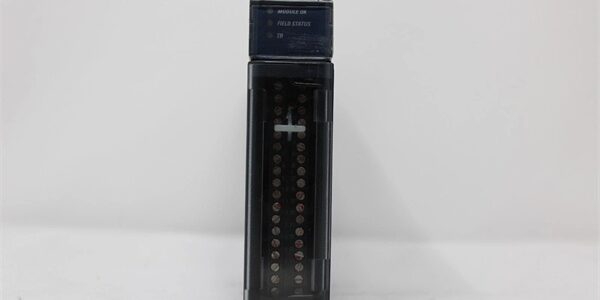
Product Core Brief
- Model: IC695ALG808
- Brand: GE
- Series: PACSystem RX3i
- Core Function: Delivers isolated configurable analog voltage and current outputs for valve, drive and actuator process control.
- Product Type: 8-Channel Isolated Analog Output Module
- Key Specs: Channel-isolated | 4 signal ranges | 8ms full-channel update rate Note: Active production hardware; new original and surplus units available globally. Requires external 24VDC field power supply.
Key Technical Specifications
- Channel Count: 8 independent isolated analog output channels
- Selectable Signal Ranges: ±10V, 0–10V, 0–20mA, 4–20mA (per-channel software configuration)
- Resolution: 14-bit (0–10V); 15-bit (±10V, 0–20mA, 4–20mA)
- Full 8-Channel Update Time: 8 ms
- Accuracy: ±0.1% of span @25°C; ±0.25% of span across rated operating temperature
- Isolation Rating: 2550 VDC, field circuits to backplane
- Maximum Load: 1350 Ω for current outputs; minimum 2 kΩ for voltage outputs
- Backplane Power: 250 mA @3.3 VDC, 17 mA @5 VDC
- External Field Power: 19.2–30 VDC nominal 24 VDC, 660 mA maximum
- Operating Temperature: 0°C to 60°C horizontal cabinet mounting
- Storage Temperature: -40°C to 85°C
- Supported Terminal Blocks: IC694TBB032, IC694TBS032
- Hot Swap Support: Yes, subject to minimum CPU firmware revision
Product Introduction
This unit generates analog control signals to modulate final control elements in continuous process applications. Every channel features galvanic isolation to suppress ground loop noise between field equipment and the PLC backplane.
The module supports configurable fail-state behavior; outputs can hold last value or drive to a predefined safe level if communications with the controller drop out.
QA & Testing SOP (Transparency Building)
- Incoming Inspection: Verify part marking and serial traceability. Inspect edge connector pins for deformation and housing cracks; check terminal block interface for corrosion.
- Live Testing: Mount into a validated RX3i rack, apply backplane and external 24VDC field power. Execute full-range ramp testing on all channels with precision load resistors over a 24-hour continuous cycle.
- Electrical Testing: Use Fluke 115 to monitor supply rails. Insulation resistance testing must exceed 10MΩ between field terminals and chassis ground.
- Firmware/Config Backup: Log module firmware revision. Capture photos of terminal wiring layout before disassembly.
- Final QC & Packaging: Place unit inside anti-static shielding. Attach dated QC test tag listing channel calibration results prior to shipment.
Installation Pitfalls & Guide (Engineer to Engineer)
❗ Firmware Minimum Requirement: Hot swap functionality fails if CPU firmware is older than v2.51. Attempting hot removal on unsupported firmware can trigger rack-wide I/O faults. ❗ Load Resistance Violation: Exceeding 1350Ω on 4–20mA channels creates clipped output and persistent module diagnostic alarms. Confirm actuator impedance before wiring. ❗ Signal Range Misconfiguration: Accidental mixing of voltage and current modes on shared wiring burns module output drivers. Always match PME channel setup to field wiring. ❗ ESD Dangers: Exposed analog circuitry is sensitive to static discharge. Unprotected handling can introduce drifting channel offset errors that appear after commissioning. ❗ External Power Dependency: The module cannot operate from backplane power alone. Loss of the 24VDC field supply forces all outputs into configured fail-safe state.
Replacement Guide:
- Pre-install: Back up hardware configuration, photograph terminal wiring, confirm CPU firmware supports hot swap.
- Removal: If hot swap qualified, unlock module latches and extract; if not, execute lockout-tagout on rack power and field 24VDC supply.
- Install: Seat the new unit fully into the backplane, lock latches, reattach terminal block and replicate all wiring connections.
- Power-on Test: Restore power, download configuration, run full-scale channel test and verify no diagnostic fault codes.
FAQ (Frequently Asked Questions)
Q: Does this unit support hot swapping? A: Yes, hot swap is available, but the host CPU must run firmware revision 2.51 or newer. Older firmware does not properly handle bus reinitialization and may trigger loss-of-module faults.
Q: Can channels run mixed signal ranges on the same module? A: Yes. Each channel can independently be set to voltage or current mode within Proficy Machine Edition. No hardware jumpers are required.
Q: Does this module support HART communication? A: No. The hardware does not implement HART modulation. Select alternative AO modules if HART-enabled field transmitters are required.
Q: What happens when external 24VDC field power fails? A: All analog outputs transition to the user-defined fail state (hold last value or preset level). Backplane power alone cannot drive field outputs.
Q: Can I use shielded cables for field wiring? A: Shielded twisted pair is recommended. Connect cable shield to cabinet protective earth at one end only to eliminate circulating ground currents.
Q: Will program configuration transfer directly from an existing unit to a replacement? A: Hardware configuration imports without modification. Always perform a full channel scale test after replacement to validate output accuracy.
Q: What diagnostic alarms can this module report? A: It detects overrange, underrange, open circuit, external power loss and internal hardware faults. All alarms populate the controller fault table for logic handling.