
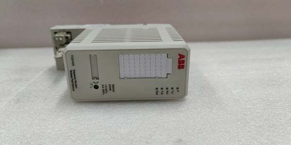
Product Core Brief
- Model: TC560V2 3BSE022178R1
- Brand: ABB
- Series: Advant OCS / DS100 PBC legacy DCS AF100 bus communication hardware
- Core Function: Converts electrical AF100 differential bus signals to multi-mode fiber for noise-free long-distance fieldbus extension
- Product Type: Rack-slotted optical bus repeater media converter PCB
- Key Specs: Dual ST fiber transceivers | 1500VAC galvanic isolation | AF100 proprietary bus protocol
- Note: Full platform end-of-life; factory sealed new units and fully cyclic load-tested surplus available for thermal power and chemical plant legacy cabinet maintenance
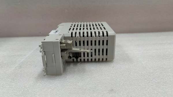
Key Technical Specifications
- Supported Bus: ABB proprietary AF100 differential parallel fieldbus
- Optical Interfaces: Dual duplex ST multi-mode fiber ports, OM1 62.5/125μm cable compatible
- Max Fiber Cable Reach: 3000 meters single segment
- Copper Bus Max Length: 2000 meters shielded twisted pair
- Isolation Rating: 1500VAC between field copper bus and fiber logic circuits
- Auxiliary Supply: 24 VDC ±10% SELV from rack backplane, 0.3A nominal draw
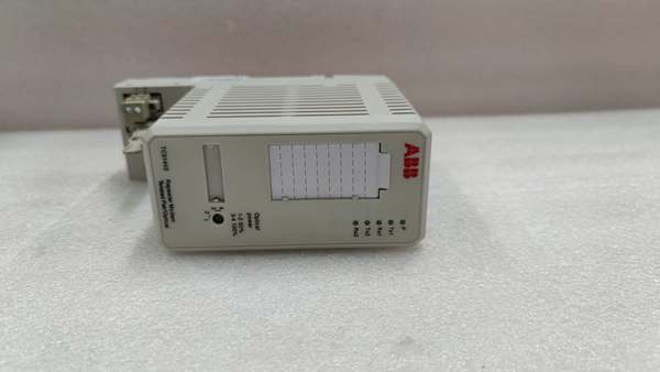
- Front Diagnostic LEDs: Green POWER, Tx transmit, Rx receive, red FAULT bus alarm
- PCB Protection: ISA S71.04 G3 conformal coating for coastal high-humidity cabinet environments
- Mechanical Mount: Standard DS100 PBC rack slot direct insertion
- Operating Temperature: -10°C to +60°C sealed cabinet; storage -40°C to +85°C
- Humidity Rating: ≤75% RH non-condensing
- Overall Dimensions: 178mm H × 140mm D × 51mm W
- Net Weight: 0.7 kg
- Compliance Standards: IEC 60255, CE certified
Product Introduction
This rack-mounted board acts as a bidirectional bus media converter, isolating noisy copper wiring near motor control centers from control room rack logic via fiber optic transmission. Its dual ST fiber ports support redundant bus topology to eliminate single communication point failure, and real-time Tx/Rx LED indicators let technicians verify live bus traffic without diagnostic software tools.
QA & Testing SOP (Transparency Building)
- Incoming Inspection: Cross-reference serial number against ABB Advant spare asset database to filter counterfeit assemblies; inspect ST fiber ferrule ports, rear backplane gold pins and front LED array with a 10x magnifier for thermal discoloration or pin corrosion; log serial numbers for full plant traceability records.
- Live Testing: Seat the unit on a DS100 test rack paired with an AC460 controller; connect dual multi-mode fiber cables and maximum-length shielded twisted pair load banks; run a continuous 24-hour cycle test including fiber cable fault injection, full bus scan validation and automatic fault trigger logging.
- Electrical Testing: Use a Fluke 115 insulation tester to verify ≥10MΩ isolation between copper bus terminals and rack chassis ground; measure PE continuity resistance below 0.5Ω.
- Firmware/Config Backup: Photograph front LED fault mapping and OEM maximum cable length limits printed on the PCB silkscreen for field wiring reference.
- Final QC & Packaging: Wipe module housing with static-dissipative microfiber cloth; cap ST fiber ports and rear backplane connector with insulating dust covers; seal the unit inside a shielding ESD bag, attach a printed QC tag with full 24-hour bus communication test timestamp, then pack into foam lined transit cartons.
Installation Pitfalls & Guide (Engineer to Engineer)
❗ Dirty ST fiber ferrules cut optical throughput drastically: Bare finger contact leaves oil residue that blocks light transmission; clean all fiber tips with OEM alcohol wipes before plugging into the transceiver ports. ❗ Unshielded twisted pair copper bus creates constant timeouts: Cable runs over 500m near variable frequency drives generate signal transients that trigger repeated bus resets. ❗ Skewed rack insertion scratches gold backplane pins: Insert the unit straight into the dedicated communication slot; angled seating creates permanent intermittent bus contact loss during cabinet thermal cycling. ❗ ESD discharge destroys fiber transceiver ICs: Static contact with PCB optical logic traces disables both Tx/Rx fiber ports, requiring full unit replacement and multi-hour plant production downtime. ❗ Hot-swap energized backplane bus creates bus parity errors: Removing the unit under live rack power disrupts clock signals and forces the paired Advant controller to cold restart, disabling all I/O scanning cycles.
4-step replacement guide
- Pre-install: Lock out and tag cabinet 24VDC auxiliary power supply for the DS100 rack; wait 10 minutes for internal backplane capacitors to fully discharge; don ESD wrist strap; capture photos of copper bus wiring, dual ST fiber cabling and rack slot position of the module.
- Removal: Disconnect all fiber optic cables and copper fieldbus wires one by one following captured photos; release front rack latch, slide the old unit straight out of the backplane slot without twisting edge connector pins.
- Install: Align the new hardware with the communication slot rails and seat fully inward until the latch clicks locked; clean fiber ferrules then re-seat dual ST fiber cables; re-terminate copper bus wiring matching photographed polarity sequence to OEM torque specs.
- Power-on Test: Restore rack 24VDC power; confirm steady green POWER LED and active Tx/Rx traffic indicators; run full bus scan to verify all remote I/O data uploads to plant SCADA without packet loss; simulate primary fiber cable pull to confirm red FAULT LED activates and logs the bus fault event to the controller history.
FAQ
Q: Can this unit operate without fiber optic cabling connected? A: It will pass local bus signals to adjacent rack I/O modules, but all remote fiber-linked I/O segments will remain offline. The optical ports are required for long-distance distributed plant layouts exceeding 2km copper cable limits. Q: Is hot-swapping supported while rack 24VDC auxiliary power remains energized? A: It is not supported. The live backplane bus carries high-speed differential signal frames; unplugging the module creates voltage transients that corrupt bus data and trigger full controller cold restarts, disrupting real-time process monitoring. Full power lockout and capacitor discharge wait time are mandatory. Q: What warranty coverage applies to stocked units? A: Factory-new original optical bus repeaters carry a 12-month OEM warranty covering dual ST fiber transceivers, copper bus isolation circuits and front diagnostic LED arrays. Load-tested surplus units come with a 6-month functional warranty. Damage from contaminated fiber ferrules, unshielded fieldbus wiring or ungrounded ESD handling voids all coverage. Q: What hardware replaces this unit for new plant DCS builds? A: New 800xA systems use CI867 fiber communication interfaces that integrate media conversion directly on the controller bus, eliminating separate rack-slotted repeaters. This hardware remains approved only for one-to-one maintenance replacement of legacy Advant OCS DS100 rack systems. Q: Will stored bus configuration settings be lost after a full cabinet power outage? A: No custom bus parameters store locally on the hardware; all timing and signal characteristics are fixed passive circuit values. Power loss does not alter operational behavior, so no manual reconfiguration is required post-replacement beyond matching physical wiring. Q: What are the most common failure modes for a faulty unit? A: Persistent red FAULT LED with undamaged fiber cabling, complete loss of Rx receive traffic with active transmit signals, severe bus scan delay under maximum copper I/O load, loss of isolation creating cross-bus signal crosstalk, blank Tx/Rx LEDs with normal 24VDC rack supply, and failure to log fiber break faults to the Advant controller event history.




