
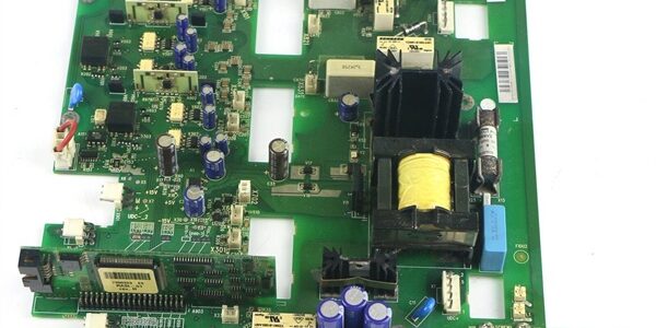
Product Core Brief
- Model: , OEM spare part code: 68597714C
- Brand: ABB Hitachi Energy
- Series: ACS800 series industrial variable frequency drive main circuit interface board
- Core Function: Critical inner converter PCB responsible for IGBT gate drive signal transmission, three-phase main current sampling, power stack temperature detection, short-circuit overcurrent protection signal feedback and internal power auxiliary conversion. It acts as the signal bridge between the NDCU/RDCU control unit and high-power IGBT power modules of ACS800 converters, supporting grid-side and rotor-side converters of wind turbine ACS800 units as well as industrial heavy-duty motor drives.
- Product Type: Main Circuit Interface Printed Circuit Board (PCB)
- Key Specs: 12 VDC internal logic power supply; integrated CT current sampling circuits; built-in NTC heatsink temperature monitoring; galvanic isolation between low-voltage control and high-power main circuits; compatible with medium & high power frame sizes of series converters
- Note: End-of-production by ABB official; limited factory-new sealed PCBs and fully bench-load-tested surplus boards are supplied for legacy wind farm, metallurgy, water treatment plant drive cabinet emergency maintenance. All boards are coated with anti-corrosion conformal coating for harsh industrial environments.
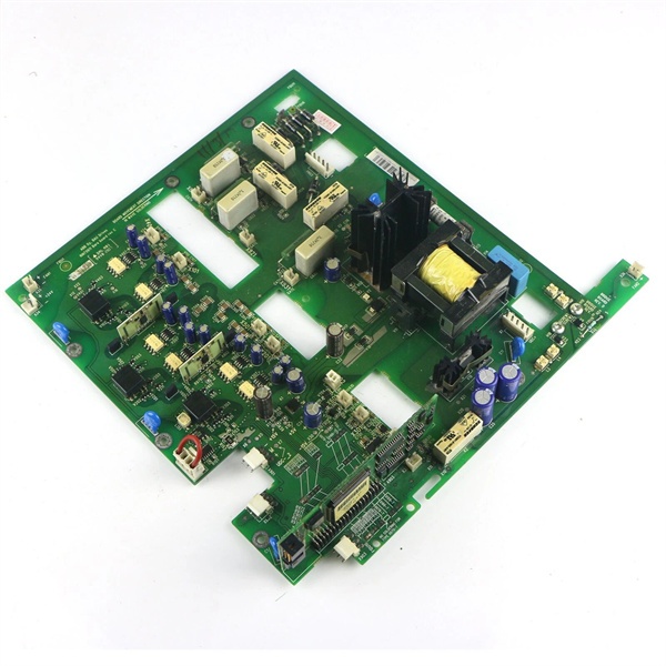
Key Technical Specifications
| Parameter | Value |
|---|---|
| Full OEM Part Code | , 68597714C |
| Internal Logic Supply | 12 VDC from converter internal auxiliary power board |
| Current Sampling Channels | 3-phase AC current galvanic sampling for IGBT overcurrent protection |
| Temperature Monitoring | NTC thermistor interface for power module heatsink overtemperature detection |
| IGBT Drive Interface | Isolated pulse signal transmission to upper/lower bridge IGBT stacks |
| Built-in Protection Logic Hardware | Instant short-circuit current lockout, overtemperature trip signal output, drive pulse loss self-diagnosis |
| Communication Link | Matches DDCS fiber bus between power stack and main control unit (NDCU/RDCU) |
| PCB Protection Coating | ISA 71.04 G3 anti-corrosion conformal coating, anti-moisture & anti-salt fog |
| Enclosure Rating | IP20 board-level protection, installed inside sealed converter cabinet |
| Operating Ambient Temperature | -20 °C to +50 °C continuous operation inside drive cabinet; derate above 45 °C |
| Storage Temperature Range | -40 °C ~ +70 °C |
| Mechanical Mounting | Fixed mounting bracket inside power unit drawer |
| Overall Board Dimensions | 215 mm L × 110 mm W × 35 mm D |
| Net Weight | Approx. 420 g |
| Compliance Standards | IEC 61800-3 EMC for variable speed drives, CE certified, RoHS compliant |
Product Introduction
The is a dedicated main circuit interface board exclusively designed for ABB series medium and high-power converters, widely deployed in wind turbine full-power converters, large industrial motor drives for fans, pumps, crushers and rolling mills.It undertakes three core core tasks of the converter power stage:
- Transmitting isolated DDCS pulse drive signals from the upper-layer NDCU/RDCU control unit to each IGBT power module to control turn-on and turn-off of power semiconductors;
- Real-time sampling of three-phase output current via built-in miniature current transformers, feeding sampled analog signals back to the control board for overcurrent, overload and phase unbalance protection calculation;
- Collecting heatsink temperature signals from IGBT modules, triggering overtemperature pre-alarm and hard trip to prevent IGBT thermal breakdown.
The board adopts full galvanic isolation design between low-voltage signal circuits and high-voltage main power circuits, effectively suppressing EMI interference generated by high-frequency switching of IGBTs. Integrated self-diagnosis circuit continuously monitors drive pulse integrity, sampling loop continuity and temperature sensor status; once any loop fails, it immediately locks IGBT output and sends fault codes to the control panel for maintenance troubleshooting.
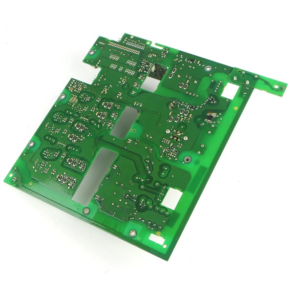
All circuit traces are covered with conformal coating to adapt to offshore wind farms, metallurgical workshops and other corrosive, high-humidity industrial environments, extending the service life of the PCB.
QA & Testing SOP (Transparency Building)
- Incoming Visual Inspection: Cross-check full part number 68597714C and serial number against ABB spare parts database to reject counterfeit mismatched boards; inspect PCB traces, sampling CTs, IGBT drive connectors and conformal coating for burn marks, salt corrosion, scratch damage or discoloration; record serial numbers and production batches for full traceability.
- Full Bench Linkage Test: Install the board into standard power unit test rack, supply stabilized internal 12VDC logic power, connect matched NDCU/RDCU control unit and simulated IGBT power stack; run 24-hour cyclic testing including IGBT pulse drive output, three-phase current sampling accuracy, overtemperature signal simulation and DDCS fiber communication linkage, verify all fault protection signals trigger normally.
- Electrical Insulation Test: Use insulation resistance tester to confirm isolation resistance ≥10 MΩ between high-power sampling circuits and low-voltage logic circuits; test chassis ground continuity resistance below 0.5 Ω.
- Firmware & Hardware Record Backup: Record hardware version of the board, photograph all terminal pin definitions and connector wiring sequences, back up the complete drive parameter group of the matched converter via DriveWindow PC tool for offline storage.
- Final QC Packaging: Wipe PCB surface with anti-static microfiber cloth, cover all gold-plated connectors with insulating dust caps, place the board into independent ESD shielding bag, attach unified printed QC test tag with technician ID and full 24-hour test runtime timestamp, then pack into foam shockproof carton for long-distance transportation.
Installation Pitfalls & 4-Step Replacement Guide
Common Installation Risks
❗ High-Voltage Residual Charge Hazard: The converter DC bus capacitor stores lethal residual high voltage after shutdown; wait for full capacitor discharge (minimum 15 minutes) before disassembling the board to avoid electric shock.❗ Connector Pin Damage Risk: Do not pull drive signal and current sampling connectors by hard wires; hold the plastic connector housing for plugging/unplugging to prevent pin bending or open circuits.❗ ESD PCB Damage: Must wear certified anti-static wrist strap during all disassembly and installation operations; bare hand contact with PCB chip traces will permanently damage sampling and drive circuits.❗ Mismatched Control Unit Firmware: Outdated NDCU/RDCU firmware cannot match the signal sampling algorithm of , leading to current measurement drift and false overcurrent trips; upgrade DriveWindow and converter firmware to matched versions before commissioning.❗ Connector Wiring Misalignment: Reverse insertion of DDCS fiber or IGBT drive connectors will cause complete power stack communication loss and converter fault shutdown; take clear photos of all wiring before removal for reference.
4-Step Board Replacement Guide
- Pre-install Preparation: Perform full lockout/tagout on the converter main AC input power, wait 15+ minutes for DC bus capacitor complete discharge, wear ESD wrist strap, photograph all fiber DDCS jumpers, IGBT drive connectors, current sampling terminals and temperature sensor wiring sequences on the board.
- Removal Operation: Unplug all signal connectors one by one according to photographed records, unscrew the fixed mounting bolts of the board bracket, take out the old PCB from the converter power drawer.
- Installation & Wiring: Fix the new board onto the original bracket, align the board position and fasten fixing bolts with standard torque; re-plug all fiber, drive and sampling connectors strictly following the photographed wiring sequence, ensure all connectors are fully locked without loose pins.
- Power-on Commissioning Test: Restore converter auxiliary control power first, upload matched firmware and drive parameter sets, perform static current sampling calibration without main power input; then close main AC power, run no-load converter test, verify three-phase current sampling value consistency, heatsink temperature reading normal and no drive pulse fault alarms.
FAQ
Q: What is the core function difference between and general control boards like RDCU-12C?A: is a main circuit power interface board, responsible for high-power IGBT drive, current sampling and power module temperature detection (high-voltage power side signal processing). RDCU-12C is the upper-layer logic control unit, only processing low-voltage communication, protection logic and human-machine interaction; the two boards must work together and cannot replace each other.
Q: Can be hot-swapped with the converter energized?A: Absolutely prohibited. The board is connected to DC bus high-voltage circuits and live IGBT drive loops; disassembly under energized conditions will cause arc flash, permanent power module breakdown and fatal electric shock accidents. Full power lockout and capacitor discharge are mandatory before replacement.
Q: What warranty applies to stocked boards?A: Factory-new original PCBs carry 12-month official ABB manufacturer warranty covering sampling circuits, IGBT drive transceivers and PCB substrate. Bench-tested surplus boards provide 6-month functional warranty; damage caused by residual high voltage shock, miswiring or ungrounded ESD handling voids all warranty terms.
Q: Has ABB stopped producing ?A: Yes, the converter platform including interface board is fully end-of-production. New wind farm and industrial drive projects adopt updated ACS880 series converters with redesigned main circuit boards; is only supplied as spare parts for legacy fleets.
Q: Will converter motor protection parameters be lost after replacing the board?A: All motor control curves, overload thresholds and fault logic settings are stored in the NDCU/RDCU control unit flash memory, not on the . Parameter backup is still recommended before replacement to avoid recalibration work caused by firmware version mismatch.
Q: What faults are usually caused by damaged ?A: Common fault codes include: overcurrent false trip without actual load short-circuit, IGBT drive pulse loss alarm, heatsink temperature reading abnormal/constant over-temperature fault, DDCS fiber communication loss between control unit and power stack, converter unable to output three-phase balanced current.





