
Product Core Brief
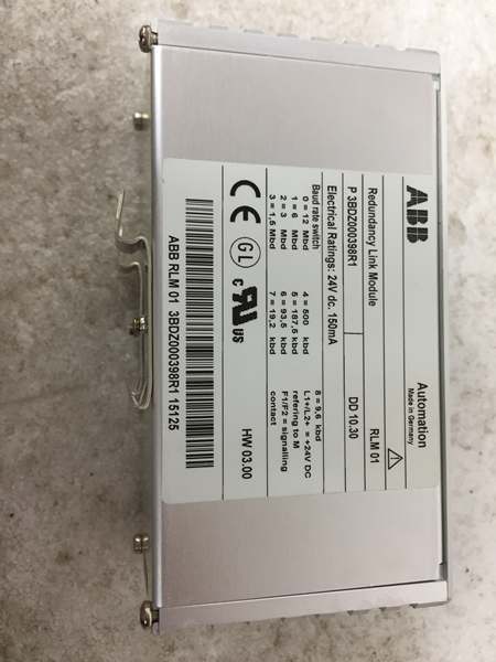
- Model: RLM01, official OEM part codes: 3BDZ000398R1, 3BDD011600R0601
- Brand: ABB Hitachi Energy
- Series: ABB 800xA / AC800M DCS PROFIBUS fieldbus infrastructure module
- Core Function: Active bidirectional PROFIBUS redundancy link module, acting as an intelligent bus switch to convert one single non-redundant PROFIBUS DP/FMS line into two mutually redundant lines (A/B), or aggregate two redundant bus cables into one single PROFIBUS interface. It allows single-port PROFIBUS field devices (drives, protection relays, remote I/O) to connect to fully redundant DCS control networks, ensuring zero communication outage if one bus cable fails. It also integrates signal repeater amplification and full three-line communication fault diagnosis.
- Product Type: DIN rail mounted PROFIBUS redundancy interface module
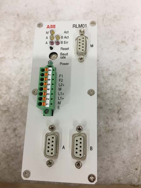
- Key Specs: 24 VDC redundant power supply; 3 x 9-pin Sub-D PROFIBUS ports (A, B, M); supports 9.6 kbps ~ 12 Mbps baud rate; transparent to PROFIBUS configuration (no slave address needed); built-in fault LED indicators + potential-free alarm relay contact
- Note: Still active production for ABB DCS system new projects and legacy plant maintenance; factory sealed new modules and fully bench-tested surplus units are widely supplied for power generation, chemical, mining, water treatment and marine automation systems.
Key Technical Specifications
| Parameter | Value |
|---|---|
| Full OEM Part Numbers | 3BDZ000398R1 / 3BDD011600R0601 |
| Supply Voltage | 24 VDC (operating range: +20 VDC ~ +33 VDC); dual redundant power terminals L1+/L2+ |
| Typical Power Consumption | 150 mA at 24 VDC, total power loss approx. 3.6 W |
| PROFIBUS Interfaces | 3 x standard 9-pin Sub-D RS485 ports (Port A, Port B = redundant bus lines; Port M = single non-redundant line) |
| Supported Baud Rates | 9.6 kbps, 19.2 kbps, 93.75 kbps, 187.5 kbps, 500 kbps, 1.5 Mbps, 3 Mbps, 6 Mbps, 12 Mbps |
| Max Nodes Per Port | Up to 31 PROFIBUS DP/FMS slaves per single port; expandable via optical repeaters |
| Isolation Rating | Functional isolation between bus circuits and power circuit, test voltage 500 Veff |
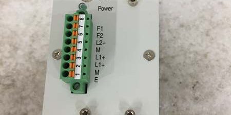
| Diagnostic Features | Front panel multi-color LED status indicators (Power, Bus A Fault, Bus B Fault, Module Run); 8-pin terminal strip with potential-free alarm relay contact for system fault signaling |
| Mechanical Mounting | Standard 35 mm DIN rail mounting; optional panel screw mounting |
| Physical Dimensions | 134 mm (H) × 56 mm (W) × 70 mm (D) |
| Net Weight | Approx. 330 g |
| Operating Ambient Temperature | 0 °C ~ +50 °C continuous operation; storage / transport: -30 °C ~ +85 °C |
| Humidity Limit | Max 75% relative humidity, non-condensing |
| Certifications | CE, UL, CSA, Germanischer Lloyd marine approval; compliant with IEC 61158 PROFIBUS standard |
Product Introduction
The ABB is a dedicated PROFIBUS redundancy converter designed for mission-critical ABB 800xA and AC800M distributed control systems, solving the compatibility issue between single-interface field equipment and fully redundant DCS bus architecture.Its core bidirectional switching logic works as follows:
- When converting 1 single line (M) to 2 redundant lines (A/B): The module duplicates all bus data to both A and B cables simultaneously;
- When aggregating 2 redundant lines (A/B) to 1 single line (M): It receives parallel data from both redundant cables, automatically selects the first valid fault-free data frame and forwards it to the M port, realizing bumpless bus switchover within microseconds if one cable is damaged, cut or shorted.
features built-in RS485 signal amplification as a PROFIBUS repeater, recovering distorted bus signals for long-distance field wiring. It continuously monitors communication activity and signal integrity on all three ports. Any failure (bus open circuit, short circuit, missing signal, power loss) triggers front panel LED alarms and closes the dry alarm contact to send fault signals to DCS or SCADA.A key advantage is full transparency to PROFIBUS configuration: no extra slave address needs to
be assigned to the , requiring no modification to existing DCS program logic during installation or replacement. It is widely deployed for redundant bus connection of variable frequency drives, MV protection IEDs, remote I/O stations, valve positioners and field transmitters in power plants, chemical factories, mining conveyor systems and offshore marine platforms.
QA & Testing SOP (Transparency Building)
- Incoming Visual Inspection: Cross-check full part number 3BDZ000398R1 and serial number against ABB official spare parts database to reject counterfeit mismatched modules; inspect Sub-D connectors, terminal blocks, PCB and enclosure for scratches, corrosion or burn damage; record serial numbers and production batches for full traceability.
- Full Bench Communication Test: Mount on standard DIN rail test bench, supply dual redundant 24VDC power, connect AC800M PROFIBUS master and simulated DP slave devices to A/B/M ports; run 24-hour cyclic communication testing including manual cable disconnection/short-circuit simulation to verify automatic redundant line switchover, fault LED alarm and relay contact trigger function, validate all baud rate compatibility.
- Electrical Insulation Test: Use insulation resistance tester to confirm isolation resistance ≥ 10 MΩ between PROFIBUS bus circuits and DC power supply terminals; test chassis ground continuity resistance below 0.5 Ω.
- Configuration Record Backup: Record module hardware revision, photograph terminal pin definitions and Sub-D port wiring standards, save test communication log data for offline reference.
- Final QC Packaging: Wipe module enclosure with anti-static microfiber cloth, cover all Sub-D ports with dust protective caps, place the unit into independent ESD shielding bag, attach unified printed QC test tag with technician ID and full 24-hour test runtime timestamp, then pack into foam shockproof carton for long-distance transportation.
Installation Risks & 4-Step Replacement Guide
Common Installation Hazards
❗ Terminating Resistor Misconfiguration: If Port A/B/M is located at the start or end of a PROFIBUS bus segment, the integrated terminating resistor inside the Sub-D connector must be enabled; missing termination will cause signal reflection and frequent communication dropouts.❗ Single Power Supply Wiring Defect: If only one L1+ power terminal is powered, a jumper wire must link L1+ and L2+ to avoid persistent power fault alarm signals.❗ ESD PCB Damage Risk: Wear certified anti-static wrist strap during disassembly and installation; bare hand contact with internal PCB traces will damage bus transceiver chips.❗ Baud Rate Mismatch Fault: All PROFIBUS devices on the same bus segment must be set to identical baud rate; inconsistent speed settings lead to total communication failure.❗ Hot-Swap Bus Cable Danger: Disconnect live PROFIBUS Sub-D cables while the module is energized will generate RS485 signal surge and damage internal bus chips; cut off module power before plugging/unplugging bus connectors.
4-Step Module Replacement Guide
- Pre-install Preparation: Lock out and tag out the 24VDC power supply for the module, wear ESD wrist strap, photograph wiring of Port A/B/M PROFIBUS Sub-D cables and L1+/L2+ power terminal wiring sequences.
- Removal Operation: Unplug all three Sub-D bus connectors one by one according to photographed records, disconnect the 8-pin power/alarm terminal block, release DIN rail mounting clip and take out the old module.
- Installation & Wiring: Clip the new module onto the DIN rail, replicate original 24VDC power wiring and PROFIBUS A/B/M bus cable connections strictly following photographed diagrams, enable bus terminating resistors on end-of-segment ports as required.
- Power-on Commissioning Test: Restore dual 24VDC power supply, check green Power RUN LED lights steadily; disconnect one redundant bus cable manually to verify automatic switchover without DCS communication loss, confirm red fault LED and alarm relay contact trigger normally during cable fault simulation, upload DCS bus diagnostic logs to confirm stable field device data transmission.
FAQ
Q: What is the difference between and ordinary PROFIBUS repeaters?A: Standard PROFIBUS repeaters only amplify bus signals and extend cable distance, without redundant line switching logic. integrates repeater function plus intelligent redundant bus conversion and automatic fault switchover, specifically designed for redundant DCS control network architecture.
Q: Can support dual redundant PROFIBUS masters?A: No. only supports line redundancy for a single master; it cannot realize master redundancy where two separate masters run independent A/B bus lines simultaneously.
Q: Is hot swapping supported for ?A: The module itself cannot be hot-swapped under energized power; full 24VDC power cut-off is mandatory before replacement. PROFIBUS cables also cannot be plugged/unplugged while the module is powered to avoid transceiver chip damage.
Q: What warranty applies to stocked modules?A: Factory-new original modules carry 12-month official ABB manufacturer warranty covering internal bus transceivers, relay alarm circuits and PCB substrates. Bench-tested surplus modules provide 6-month functional warranty; damage caused by miswiring, bus surge voltage or ungrounded ESD handling voids all warranty terms.
Q: Has ABB discontinued production?A: No, remains active mass production for ABB 800xA DCS new construction projects; it is still the standard fieldbus redundancy solution for PROFIBUS DP networks.
Q: What typical faults indicate a failed module?A: Common failure symptoms: Persistent bus fault LED alarms with intact field cables, frequent random communication dropouts of downstream PROFIBUS slaves, no automatic switchover after one redundant cable is cut, loss of alarm relay output function, module unable to boot up after power supply restoration.





