
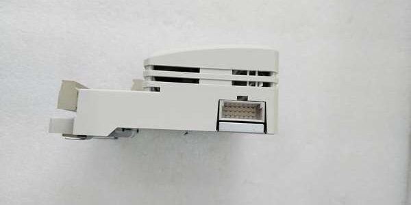
Product Core Brief
- Model: AO801, OEM part number 3BSE008522R1
- Brand: ABB
- Series: S800 compact analog output module for System 800xA AC800M DCS
- Core Function: Convert digital control values to 0/4–20mA analog signals for modulating control valves and field actuators
- Product Type: Plug-in S800 I/O module, mates with TU810V1 passive termination unit
- Key Specs: 8 unipolar output channels | Max 850Ω load resistance | OSP output safe position logicNote: Inventory stock is New Surplus with intact factory anti-static packaging, full OEM technical documentation included.
Key Technical Specifications
- Auxiliary field supply: 24VDC ±10V, maximum 200mA combined module draw
- Supported output signal ranges: 0–20mA, 4–20mA unipolar current loops
- Maximum permissible load resistance per channel: 850 Ohms
- Internal resolution: 12-bit digital-to-analog conversion
- Integrated diagnostics: Channel short-circuit detection, module undervoltage warning, open-loop fault flagging
- Fail-safe behavior: OSP (Output Safe Position) locks outputs to predefined values during ModuleBus communication loss
- Circuit protection: Per-channel short-circuit foldback limiting, reverse supply voltage blocking
- Hot-swap rating: Fully hot-swappable on live S800 ModuleBus racks
- Operating temperature range: -20°C to +55°C full load; linear performance derate above 55°C
- Storage environmental limits: -40°C to +70°C, 5%–95% RH non-condensing
- Physical dimensions: 45mm W × 110mm H × 102mm D; unit mass 0.21kg
- Compliance standards: CE, UL, RoHS, IEC 61000-6-2 Class A industrial EMC
- System compatibility: AC800M System 800xA S800 racks; incompatible with Symphony HR, UNITROL, AC500 PLC, IRC5 robot hardware
Product Introduction
This analog output module translates digital setpoints from the AC800M controller into standard 4–20mA current loops to position modulating valves, dampers, and variable-speed actuator drives in continuous process plants.Built-in short-circuit hardware protection prevents permanent channel damage from field wiring faults, while OSP logic eliminates uncontrolled actuator drift if the ModuleBus trunk loses connectivity.
QA & Testing SOP (Transparency Building)
- Incoming Inspection: Cross-reference serial numbers against ABB component trace databases; inspect rear gold mating contacts for oxidation, front status LED segment integrity, plastic housing for micro-cracks; validate unbroken factory static packaging seal for surplus inventory units.
- Live Testing: Mate the module to a TU810V1 termination base on a DIN rail test bench paired with an AC800M CPU simulator and adjustable resistive load banks up to 850Ω; run uninterrupted 24-hour cyclic full-range 4–20mA signal generation across all 8 channels; use a Fluke 115 to log steady 24VDC field supply voltage through the full test cycle.
- Electrical Testing: Perform 50VAC dielectric isolation testing between output signal loops and internal ModuleBus logic ground; pass threshold set at >10MΩ insulation resistance; inject short-circuit and reversed 24VDC supply faults to confirm hardware lockout activates without damaging DAC semiconductors.
- Firmware/Config Backup: No user-modifiable onboard firmware; photograph channel terminal pin assignments and record factory OSP default values for field commissioning reference.
- Final QC & Packaging: Torque all TU810V1 terminal screw connections to OEM 0.5–0.6Nm torque specifications; enclose the module in static-dissipative foam; attach a printed QC tag listing serial number and completed test metrics before carton sealing.
Installation Pitfalls & Guide (Engineer to Engineer)
❗Firmware Mismatch Risk: Outdated AC800M controller firmware lacks calibrated DAC timing profiles for the module. Fault outcome: Non-linear analog output ramps, unsteady valve modulation during process load transients. Mitigation: Flash matching validated firmware revisions to the CPU before rack power-up; archive compatible firmware files to plant engineering servers.❗Excessive Field Load Resistance Risk: Connecting transmitters or actuators with total loop resistance above 850Ω clips full-scale 20mA output. Fault outcome: Valve cannot reach 100% open position, incomplete process modulation range. Mitigation: Calculate total cable + actuator resistance before loop wiring; add signal repeaters for runs exceeding resistance limits.❗Platform Incompatibility Risk: Attempting to install the module into Symphony HR or UNITROL racks creates mismatched backplane pinouts and unregulated supply exposure. Fault outcome: Burned DAC output circuits, permanent channel failure. Mitigation: Only deploy the unit within dedicated distributed I/O racks paired with TU810V1 termination bases.❗Shared Common Rail Wiring Error: Jumping negative return lines across multiple output channels creates cross-loop signal crosstalk. Fault outcome: Fluctuating valve position drift when adjacent channels ramp simultaneously. Mitigation: Maintain isolated return wiring for every individual current loop per the TU810V1 wiring schematic.❗ESD Dangers: Low-humidity chemical plant control room air generates static charge that damages delicate DAC integrated circuits on the PCB. Field service logs show ungrounded handling creates intermittent output offset faults that require 4–10 hours of loop diagnostic labor to isolate. Mitigation: Establish direct contact with bare cabinet chassis ground metal for three full seconds before touching rear mating contacts or field terminal blocks.
4-Step Replacement Guide
- Pre-install: Set the controller to manual hold mode to lock all valve setpoints; photograph all 4–20mA actuator loop wiring assignments on the TU810V1 base.
- Removal: Unlatch the module from the termination unit by squeezing side release tabs and pulling straight outward off gold mating contacts; leave all field wiring terminated to the base to eliminate full retermination labor.
- Install: Align the new unit’s rear mating contacts with the base and push fully seated until side latches audibly lock; replicate loop resistance calculations and OSP parameter settings within Control Builder M to match original process requirements.
- Power-on Test: Energize 24VDC field supply and rack ModuleBus; send full-range 4–20mA setpoint commands to all 8 channels via the controller simulator and confirm linear, unclipped output current values with zero short-circuit fault flags accumulating during 30 minutes of idle loop testing before restoring live process control logic.
FAQ (Frequently Asked Questions)
Q: Can this unit directly replace newer AO810 series analog output hardware without control logic edits?A: No, AO810 variants support HART communication and higher load resistance ratings, with different terminal pinout mapping. Direct swap requires full rework of field loop wiring and Control Builder M channel configuration.Q: Does hot-swap capability remove the requirement to set the controller to manual hold mode during replacement?A: Hot-swap only protects the module’s internal circuits from power surge damage; it does not maintain steady analog output values during the swap window. Manual hold mode remains mandatory to prevent unplanned valve stroke movement.Q: What warranty coverage applies to surplus stocked units?A: A 12-month limited warranty only covers factory manufacturing defects. Damage from over-resistance field loops, ungrounded ESD handling, cross-platform rack installation, or sustained channel short-circuits is excluded from warranty claims.Q: Can multiple modules share a single 24VDC auxiliary power circuit in one rack?A: Multiple units may share one 24VDC supply only if the supply unit maintains 20% extra current headroom above total combined module power draw. Independent auxiliary feed wiring is recommended for racks with five or more installed analog output modules to eliminate voltage sag during simultaneous full-scale ramping events.Q: Is this analog output module rated for Class 1 Div 2 hazardous cabinet deployment inside refinery MCC rooms?A: No, the open plastic DIN rail module housing lacks intrinsic safety certification for flammable vapor environments. ABB supplies separate IS-certified analog I/O hardware for hazardous area process installations.Q: What function does the OSP fail-safe mode perform during communication loss?A: OSP stores a fixed mA value per channel configured in Control Builder M. If ModuleBus polling stops, each output locks to this pre-set current to stop uncontrolled valve travel until bus communication recovers.Q: What long-term upgrade path exists as this component reaches ABB end-of-support status?A: Modern System 800xA deployments use AO810V2 HART-enabled analog output modules for new cabinet builds. Retrofit swaps require recalculating field loop resistance and reconfiguring all analog channel parameters in the DCS control database.





