
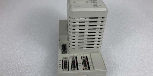
Product Core Brief
- Model: CI810B, OEM part number 3BSE020520R1
- Brand: ABB
- Series: S800 I/O AF100 fieldbus communication interface for System 800xA
- Core Function: Bridge AC800M controller ModuleBus to AF100 twisted-pair fieldbus for remote S800 I/O clusters
- Product Type: DIN rail mount plug-in fieldbus master module
- Key Specs: Integrated isolated TWP modem | Single/dual redundant operation | Hot-swap capableNote: New Surplus inventory, factory sealed anti-static packaging, full OEM technical support available.
Key Technical Specifications
- Auxiliary operating supply: 24VDC ±10%, 145mA typical power draw
- Supported fieldbus: ABB AF100 twisted-pair (TWP), 1.5Mbps maximum baud rate
- Galvanic isolation: 500VAC separation between ModuleBus backplane and AF100 trunk ports
- Cluster capacity: Up to 12 S800 I/O modules per local ModuleBus segment
- Redundancy mode: Supports standalone single unit or dual redundant paired installation
- Hot-swap certification: Fully hot-swappable without full rack power shutdown
- Diagnostic indicators: Front-panel RUN, FAULT, bus activity LED array
- Operating temperature range: -20°C to +55°C full bus load; linear performance derate above 55°C
- Storage limits: -40°C to +70°C, 5%–95% RH non-condensing
- Physical dimensions: 46mm W × 132mm H × 65mm D; unit mass 0.14kg
- Compliance standards: CE, UL, RoHS, IEC 61000-6-2 Class A industrial EMC
- System compatibility: AC800M System 800xA S800 racks; incompatible with Symphony HR, UNITROL, AC500, IRC5 robot hardware
Product Introduction
This fieldbus master links local I/O racks to long-distance twisted-pair trunks, eliminating fiber modem hardware for mid-range distributed I/O layouts.Built-in galvanic isolation blocks ground-loop noise from MCC wiring runs, reducing unplanned analog signal drift alarms during grid switching events.
QA & Testing SOP (Transparency Building)
- Incoming Inspection: Cross serial numbers against ABB component trace databases; inspect terminal spring tension, front LED segment integrity, DIN rail latch structural condition; verify unbroken factory static packaging seal for surplus stock.
- Live Testing: Mount the module to a DIN rail test bench paired with an AC800M CPU simulator and full 12-slot I/O load bank; run 24-hour continuous cyclic data polling at maximum 1.5Mbps baud rate; use a Fluke 115 to log stable 24VDC auxiliary supply voltage through the full test cycle.
- Electrical Testing: Perform 500VAC hipot insulation testing between trunk terminals and ModuleBus logic ground; pass threshold set at >10MΩ insulation resistance; inject reversed DC supply voltage to confirm hardware reverse-polarity lockout activates without damaging TWP transceiver chips.
- Firmware/Config Backup: Record factory interface firmware revision via Control Builder M; photograph rotary station address dial positions to document factory node assignments for commissioning reference.
- Final QC & Packaging: Torque all terminal screw connections to OEM torque values; enclose the module in static-dissipative foam; attach a printed QC tag listing serial number and completed test metrics before carton sealing.
Installation Pitfalls & Guide (Engineer to Engineer)
❗Firmware Mismatch Risk: Outdated AC800M CPU firmware lacks calibrated bus timing parameters for the module. Fault outcome: Intermittent loss of entire remote cluster data, unresponsive analog/digital process points in HMI. Mitigation: Flash matching validated firmware revisions to the AC800M controller before rack power-up; archive compatible firmware files to plant engineering servers.❗Duplicate Node Address Risk: Matching rotary dial station IDs across separate communication units on one trunk creates bus arbitration collisions. Fault outcome: Fluctuating analog readings, random discrete fault counter accumulation across remote I/O racks. Mitigation: Photograph the address dial position on the old hardware before removal; assign unique 1–31 node IDs per wiring schematics.❗Platform Incompatibility Risk: Attempting to install the module into Symphony HR or UNITROL racks creates mismatched backplane pinouts and unregulated supply exposure. Fault outcome: Burned ModuleBus interface circuits, permanent transceiver failure. Mitigation: Only deploy the unit within dedicated distributed I/O racks.❗Missing Termination Resistor Risk: Omitted 120Ω termination at the final trunk node generates signal reflection noise at baud rates above 500kbps. Fault outcome: Rising bus fault counters during heavy process load transients. Mitigation: Activate onboard termination switch only on the first and last nodes of each trunk segment.❗ESD Dangers: Low-humidity process control room air generates static charge that damages delicate TWP transceiver semiconductors on the PCB. Field logs show ungrounded handling creates intermittent cluster dropout faults that require 6+ hours of diagnostic labor to isolate. Mitigation: Establish direct contact with bare cabinet chassis ground metal for three full seconds before touching terminals or rack slot mating contacts.
4-Step Replacement Guide
- Pre-install: Set the controller to manual hold mode; photograph twisted-pair trunk wiring and rotary station address dial position on the faulty hardware.
- Removal: Disconnect all trunk wiring one terminal at a time and label conductors; squeeze the DIN rail bottom latch and slide the faulty unit straight upward off the mounting rail without bending internal ribbon connectors.
- Install: Clip the new unit fully onto the TS35 DIN rail until the ground latch audibly locks; replicate the photographed rotary station address setting and reterminate all trunk wiring to match original pin assignments exactly.
- Power-on Test: Energize 24VDC auxiliary rack power; initiate continuous bus polling from Control Builder M and confirm zero communication fault counters accumulate during 30 minutes of idle cluster polling before enabling full process control logic.
FAQ (Frequently Asked Questions)
Q: Can this unit directly replace older CI810, CI810A or CI810V2 hardware without control logic edits?A: Yes, all CI810 hardware revisions share identical pinout, ModuleBus communication timing and mechanical DIN rail footprint. No modifications to Control Builder M I/O configuration or control logic are required for cross-revision swap.Q: Does hot-swap operation eliminate the need to set the controller to manual hold mode during replacement?A: Hot-swap only protects the module’s internal circuits from power surge damage; it does not prevent temporary data loss for the connected cluster. Manual hold mode remains mandatory to avoid unregulated valve or actuator state changes mid-swap.Q: What warranty coverage applies to surplus stocked units?A: A 12-month limited warranty only covers factory manufacturing defects. Damage from missing bus termination resistors, duplicate node addresses, ESD mishandling, or cross-platform rack installation is excluded from warranty claims.Q: Can multiple communication units share a single twisted-pair trunk segment?A: The bus supports up to 31 unique node addresses on one unbroken trunk line. Each installed unit must carry a distinct rotary dial ID to avoid bus conflict events.Q: Is this fieldbus module rated for Class 1 Div 2 hazardous cabinet deployment inside refinery MCC rooms?A: No, the open DIN rail plastic housing lacks intrinsic safety certification for flammable vapor environments. ABB supplies separate IS-certified communication hardware for hazardous area process installations.Q: Can dual redundant units be mounted in one rack for high-availability critical process loops?A: Yes, paired units can be configured for media redundancy via Control Builder M. The system executes bumpless bus failover if one unit loses trunk communication without disrupting live process values.Q: What long-term upgrade path exists as this component reaches ABB end-of-support status?A: Modern System 800xA deployments use CI840A PROFIBUS or CI845 Ethernet communication modules in place of hardware. Full rack migration and I/O bus reconfiguration are required for a direct functional retrofit.





