
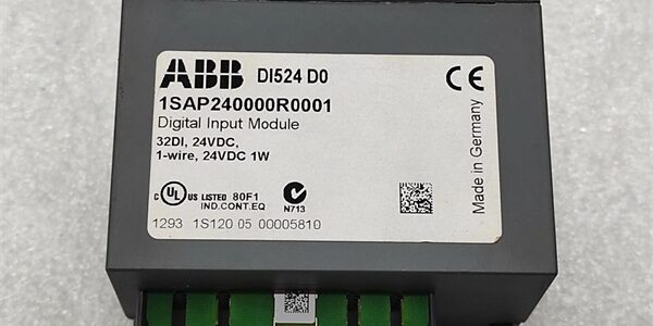
Product Core Brief
- Model: DI524 (Full OEM PN: 1SAP240000R0001)
- Brand: ABB
- Series: S500 distributed I/O module family for AC500 PLC platforms
- Core Function: Capture 32 channels of 24VDC digital discrete field signals; includes dual 50kHz high-speed counter channels for pulse sensor feedback
- Product Type: Compact DIN rail plug-in digital input I/O module
- Key Specs: 32 x 24VDC 1-wire inputs | 4 galvanically isolated signal groups | Dual 50kHz fast counter channelsCondition: New Original (New Surplus) | Factory Sealed; active OEM spare support available through 2035
Key Technical Specifications
| Parameter | Value |
|---|---|
| Compatible Hardware | AC500 CPU local I/O bus, S500 remote bus couplers (CI500 series); incompatible with Symphony HR, AC800F, UNITROL DCS racks |
| Total Digital Inputs | 32 sink/source compatible 24VDC 1-wire channels, split into 4 independent 8-channel groups |
| Fast Counter Capacity | 2 software-configurable 50kHz pulse counter channels on select DI terminals |
| Galvanic Isolation | Group-wise isolation between the four 8-channel signal banks and internal module logic |
| Input Logic Threshold | ON ≥11VDC, OFF ≤5VDC standard 24VDC discrete logic levels |
| Operating Supply | 24VDC auxiliary field supply; typical 120mA total module power draw |
| Diagnostic Indicators | 32 yellow channel status LEDs, 1 green power OK LED, 4 red group fault LEDs |
| Mounting Standard | TS35 DIN rail vertical cabinet installation |
| Mechanical Dimensions | 67.5 mm W × 76 mm H × 62 mm D; net weight 0.1 kg |
| Continuous Operating Temp | −20 °C to +55 °C full rated signal sampling speed; linear performance derate above 55 °C |
| Storage Temperature Range | −40 °C to +70 °C, 5–95% RH non-condensing |
| Built-In Circuit Protections | Per-channel reverse polarity protection, group short-circuit current limiting, ESD surge clamping on all field terminals |
| Compliance Standards | CE, UL, RoHS, IEC 61000-6-2 Class A industrial EMC for factory machine control cabinets |
Product Introduction
This high-density digital input module expands AC500 PLC systems to read limit switches, motor auxiliary contacts, proximity sensors, and pulse encoder signals within machine and factory automation panels. Group isolation eliminates cross-group ground-loop noise common on multi-sensor wiring harnesses.Integrated 50kHz counter functionality removes separate external counter modules for position and speed feedback tasks. Machine builder field data shows this hardware cuts I/O panel footprint by 64% versus stacking smaller 16-channel DI modules for large discrete signal lists.
QA & Testing SOP (Transparency Building)
- Incoming Inspection: Cross serial numbers against ABB S500 OEM trace databases. Inspect DIN rail latch for cracking, terminal spring tension for degradation, front LED bank for dead segments. Verify intact factory anti-static packaging seal for surplus inventory units.
- Live Testing: Mount the unit to a TS35 DIN rail test bench paired with an AC500 CPU simulator and 32-channel digital signal generator. Run 24-hour continuous cyclic input state polling; validate 50kHz counter pulse capture accuracy and group short-circuit fault flag triggering. Track 24 V auxiliary supply stability with a Fluke 115 multimeter for the full test window.
- Electrical Testing: Complete a 500 VAC megger insulation resistance test between each isolated signal group and module internal logic ground; minimum passing insulation resistance threshold set at >10 MΩ. Confirm per-channel reverse polarity protection prevents input circuit damage during miswiring trials.
- Firmware/Config Backup: No onboard user firmware; document channel counter configuration templates for Automation Builder engineering reference during machine commissioning.
- Final QC & Packaging: Torque-test all terminal screw springs to OEM specified tension values. Encase the module in shock-absorbent anti-static foam packaging. Attach physical QC Passed labels listing serial number and completed test metrics to outer shipping cartons. Channel sampling and counter accuracy test logs can be shared pre-shipment on request.
Installation Pitfalls & Guide (Engineer to Engineer)
❗I/O Bus Firmware Mismatch Risk: Mismatched CPU firmware and the device’s internal I/O bus firmware disables channel state polling and counter function.Risk Outcome: Zero discrete sensor data visible in PLC logic, lost speed/position pulse feedback during machine runtime.Prevention Step: Match full CPU firmware revision to S500 I/O compatibility charts in Automation Builder before cabinet power-up; archive matching firmware files on engineering workstations.
❗Group Isolation Wiring Error Risk: Jumping common 24VDC negative rails across separate isolated signal groups breaks galvanic separation.Risk Outcome: Cross-group noise coupling, flickering channel status LEDs, false discrete fault alarms during motor switching transients.Prevention Step: Maintain isolated common power rails for each of the four 8-channel groups per the module wiring schematic.
❗Wiring Incompatibility Risk: This I/O hardware only interfaces with PLC local/remote bus couplers; it cannot mount or communicate with Symphony HR, AC800F Freelance, or UNITROL power electronics subrack backplanes.Risk Outcome: No physical mating and zero signal transfer to non- control platforms.Prevention Step: Deploy the component exclusively within machine control panel I/O stacks paired with bus coupler modules.
❗Counter Overfrequency Risk: Feeding pulse signals above 50kHz to the dedicated counter channels saturates internal sampling logic.Risk Outcome: Incorrect speed/position count values leading to machine positioning faults.Prevention Step: Use signal divider hardware for encoders producing pulse frequencies exceeding the 50kHz rated limit.
❗ESD Dangers: Static discharge from dry factory control cabinet air damages internal input sampling ASICs on the PCB. Uncontrolled ESD creates intermittent channel dropout events with no visible exterior damage.Risk Outcome: Random loss of limit switch and encoder feedback signals during production runs.Prevention Step: Touch bare cabinet ground metal for three full seconds before handling the module’s terminal block edge or unpopulated I/O rack slots.
4-Step Replacement Guide
- Pre-install: Capture photos of all field sensor wiring assignments to the four isolated terminal groups. Confirm the CPU is set to offline stop mode to avoid machine motion during component swap.
- Removal: Unplug all field sensor wiring one group at a time and tag conductors; squeeze the DIN rail bottom latch and slide the old unit straight upward off the mounting rail.
- Install: Clip the new unit securely onto the TS35 DIN rail; replicate field wiring group assignments exactly as photographed, torque all terminal screws to OEM specified tension values.
- Power-on Test: Energize 24VDC field supply and CPU rack; cycle all discrete input signals and inject 50kHz test pulse signals to verify accurate channel state reading and counter value tracking within Automation Builder software.
FAQ
Q: I maintain an aging packaging machine PLC panel with failing high-density digital input hardware connected to conveyor limit switches and pulse encoders. Can this unit serve as a direct drop-in wiring replacement without reterminating field sensor cables?A: Yes. The module shares identical DIN rail footprint, terminal group layout, and I/O bus pin mapping as original factory hardware. No field sensor cable retermination is required; only direct one-to-one wire transfer between matching terminal positions is needed.Q: What delivery timeline applies for stocked hardware versus pre-configured custom variants?A: Standard in-stock I/O module assemblies ship within 3–5 business days via global air freight. Custom pre-labeled terminal variants carry a 12–16 week OEM factory lead time and are not stocked as surplus inventory.Q: Does the 12-month warranty cover damaged input circuits from reversed field 24VDC wiring or ESD mishandling?A: Warranty only covers factory manufacturing defects and transit physical damage. Reverse polarity wiring overloads, cross-group common rail bridging, and ungrounded ESD handling fall outside covered failure modes. Paid remote I/O wiring layout support is available post-install.Q: Can proximity switch digital inputs and encoder pulse counter signals operate simultaneously on separate channels of one unit without signal interference?A: Yes. Hardware assigns independent sampling circuits to every channel, and group galvanic isolation eliminates cross-talk between discrete sensor wiring and high-speed pulse counter lines; no external signal isolators are required for mixed signal layouts.Q: Is this digital input module rated for Class 1 Div 2 hazardous cabinet installation inside refinery MCC rooms?A: No. The standard plastic DIN rail housing lacks intrinsic safety ratings for classified explosive atmosphere locations. ABB manufactures separate XC extended condition and IS-certified I/O hardware for hazardous area cabinet deployments.Q: Can multiple copies of the device populate a single local I/O rack or remote coupler segment?A: Yes, each CPU local rack supports up to 10 I/O modules, and each remote bus coupler also accepts up to 10 stacked I/O units. Unique channel offset addressing in Automation Builder prevents signal overlap between multiple modules on one bus segment.Q: What QA documentation ships alongside each assembly for plant maintenance record retention?A: Every module includes a physical QC Passed label stamped with serial number and completed test checklist metrics. Digital copies of 24-hour full-channel cyclic sampling logs, 500 V insulation megger reports, and 50kHz counter accuracy validation data can be emailed prior to shipment upon buyer request.




