
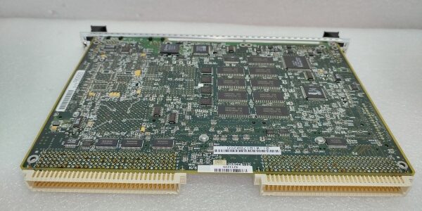
Product Core Brief
- Model: MVME147-013A
- Brand: Motorola Computer Group (Emerson / Artesyn Embedded)
- Series: Single-High 6U VMEbus 68K legacy SBC family
- Core Function: Auxiliary VME subsystem controller for vintage 200mm semiconductor etch tools, handling low-speed analog DAQ, discrete valve sequencing, and remote I/O rack polling
- Product Type: Single-height 6U VMEbus SBC, MC68030 architecture, integrated SCSI, Ethernet, multi-serial I/O routed via P2 rear connector
- Key Specs: 25MHz MC68030 + MC68882 FPU | 16MB parity-protected DRAM | 4KB battery-backed NVRAM/RTC | A32/D32 VME master capability
- Note: OEM full end-of-life; only fully refurbished bench-tested inventory exists, zero factory-new surplus. Incompatible with PowerPC-based TCP9400/Kiyo software stacks.
Key Technical Specifications
- Main Processor: MC68030 32-bit CPU @ 25MHz, integrated unified instruction/data cache, full MMU
- Floating Point Coprocessor: MC68882 hardware FPU for sensor math calculation acceleration
- Main Memory: 16MB parity-checked DRAM; parity logic detects single-bit runtime memory errors
- Non-Volatile Storage: Four EPROM/Flash boot sockets; M48T18 real-time clock module with 4KB lithium battery-backed SRAM
- VME Bus Controller: GCC ASIC supporting A16/A24/A32 addressing, D8/D16/D32 block transfers, full VME system arbitration master
- Onboard Peripherals:
- Four multi-protocol EIA-232-D serial channels (P2 rear transition routing)
- Centronics-compatible parallel printer I/O port
- DMA-enabled SCSI-2 controller for local recipe log storage
- 10Mbps AUI Ethernet transceiver header
- Timing Hardware: Two 16-bit programmable tick timers + hardware watchdog fail-safe timer
- Power Consumption: 12–18W steady full-load draw from VME P1/P2 backplane +5V / ±12VDC rails
- Mechanical Form Factor: Single-height 6U VME Eurocard, dual plastic ejector latches, all field I/O via P2 rear connector
- Operating Temperature: 0°C to +55°C with forced cabinet airflow; conformal coated variant rated -40°C to +85°C
- Compliance Standards: CE, UL, FCC Class A, SEMI S2 certified for legacy 200mm front-end manufacturing hardware
Product Introduction
This vintage 68K VME controller supported secondary automation tasks on pre-TCP9400 200mm Lam etch platforms, managing low-frequency analog and discrete I/O workloads unsuitable for later PowerPC SBC architectures.Fully integrated onboard SCSI, Ethernet, and quad serial ports eliminate extra VME I/O slots for legacy rack layouts, while battery-backed SRAM retains sensor scaling and interlock thresholds through full chassis power cycles. The MC68030 architecture lacks throughput for synchronized multi-axis wafer robot motion control.
QA & Testing SOP (Transparency Building)
- Incoming Inspection: Cross-reference serial numbers against OEM legacy component databases; visual inspection for swollen lithium backup batteries, cracked P2 connector pins, and corroded solder joints. All DIP switch bank positions photographed pre-cleaning.
- Live Bench Testing: Mount to full VME backplane chassis with Fluke 115 tracking rail voltage stability; 24-hour continuous load test running synthetic analog polling and SCSI data logging workloads matching legacy tool runtime profiles.
- Electrical Testing: Megger insulation tester verifies serial/parallel field I/O isolation exceeds 10MΩ; measure M48T18 battery terminal voltage to validate remaining charge life.
- Firmware & Config Backup: Flash validated MVME147Bug diagnostic firmware matching legacy 68K RTOS releases; dump complete NVRAM calibration tables to encrypted archive for post-install recovery workflows.
- Final QC & Packaging: Replace expired lithium backup battery as mandatory refurbishment step; coat exposed connector pins with anti-tarnish compound, wrap in anti-static foam, affix printed QC tag with battery voltage and full POST test results before sealed ESD bag packaging.
Installation Pitfalls & Guide (Engineer to Engineer)
❗ Architecture Mismatch Risk: The unit uses Motorola 68030 instruction set, incompatible with all VxWorks BSPs compiled for MVME2400/MVME5500 PowerPC hardware. Installing into TCP9400 racks triggers unbootable chassis and permanent VME bus handshake failures.❗ Expired Backup Battery Hazard: Original lithium M48T18 cells degrade after 8–10 years shelf life; dead batteries erase all NVRAM calibration data within 30 minutes of full power loss. Refurbished stock ships with fresh replacement RTC modules.❗ Serial Port Interrupt Contention Risk: All four rear serial channels share two primary VME interrupt levels. Running three or four high-speed Modbus polling streams creates interrupt contention, cutting analog scan throughput by 65%. Photograph original serial wiring assignments before removal.❗ P2 Rear Wiring Pinout Difference: MVME712 transition boards designed for 68K SBCs carry distinct signal assignments vs PowerPC rear transition modules. Cross-check OEM wiring schematic before terminating analog sensor cables to avoid shorted input circuits.❗ Catastrophic ESD Damage Risk: Unshielded cache logic is significantly more ESD-sensitive than later PowerPC hardware; grounded wrist strap and conductive anti-static mat mandatory before touching PCB traces or edge connectors.4-Step Replacement Guide:
- Pre-install: Export all legacy auxiliary chamber calibration sets via tool HMI; execute SEMI S2 lockout-tagout, vent chamber vacuum and disable RF power supplies.
- Removal: Release dual ejector latches evenly to avoid bent P1/P2 backplane pins; record DIP switch bank settings, disconnect P2 transition wiring harness fully before extracting the board.
- Install: Seat the new unit parallel to the backplane for even pin engagement, restore DIP switch positions, reattach full P2 rear signal wiring harness.
- Power-on Test: Apply standby low voltage first, validate MVME147Bug POST completes with zero memory parity faults, run 30-minute continuous serial DAQ polling to confirm stable telemetry capture.
FAQ (Frequently Asked Questions)
Q: Can this unit replace MVME2434 or MVME5500 as primary chamber master for TCP9400/Kiyo 300mm tools?A: Zero cross-compatibility at firmware/OS layer. The CPU cannot execute PowerPC-targeted VxWorks binaries used on modern Lam etch platforms. Even with physical slot fit, tool software cannot initialize VIOP motion boards or gigabit Ethernet subsystems.Q: Does this SBC support hot-swapping while the chamber remains pressurized and RF generators active?A: The GCC VME ASIC lacks modern hot-swap power sequencing logic. Live removal injects large voltage transients into the backplane, corrupting NVRAM calibration data and risking permanent damage to adjacent VME I/O boards. Full chassis power-down required before extraction.Q: What warranty coverage applies to refurbished stock of this legacy SBC?A: All available inventory is refurbished with a 4-month limited functional warranty. Coverage excludes gradual lithium RTC battery discharge over time; fresh replacement M48T18 modules fitted during refurbishment carry only a 90-day service guarantee. No factory-new OEM stock exists for this model.Q: Will swapping this controller erase stored analog sensor scaling and valve interlock thresholds?A: All calibration data resides in the board’s M48T18 battery-backed SRAM. If the onboard lithium cell fully depleted during storage, all offset tables will be lost after power cycling. Export full parameter backup before disassembly regardless of measured battery voltage.Q: Can this hardware operate on vintage 200mm Lam tools running OS9 or VxWorks 5.x 68K builds?A: Fully compatible with original 68K-targeted real-time OS releases for older 200mm etch hardware. No driver patches required as long as serial port interrupt mapping matches the removed original unit.Q: What expected service window applies to refurbished units in a 24/7 fab environment?A: Target replacement window sits at 30,000 operating hours. Aging GCC VME bus ASICs develop timing drift under continuous cabinet heat and 13.56MHz RF exposure, raising analog telemetry noise floor and triggering frequent false interlock alarms.Q: How many serial Modbus devices can reliably run simultaneously on this board’s four serial ports?A: Maximum stable configuration is two active Modbus polling streams; four serial channels are physically present, but limited interrupt bandwidth degrades scan accuracy when fully populated with high-frequency transducer polling. Separate interrupt level reconfiguration required for three or four connected serial peripherals.





