
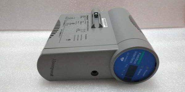
Product Core Brief
- Model: CC- (OEM drawing PN: 51405044-175)
- Brand: Honeywell
- Series: Experion PKS C300 Series-C FIM4 (4-link FOUNDATION Fieldbus Interface Module)
- Core Function: Acts as dedicated communication bridge between C300 controller and FOUNDATION Fieldbus H1 smart transmitters, valve positioners, and analyzers; offloads fieldbus scheduling and device diagnostics from the main CPU to preserve deterministic control scan performance
- Form: Vertical hot-swappable rack plug-in module, passive slotted aluminum heat dissipation, IO Link backplane bus communication
- Mandatory Pairing: Requires CC-TFB401 dedicated fieldbus termination assembly; Type 5 shielded interconnect cable max single segment run length 30 meters
- Key Built-In Specs: 4 isolated H1 31.25 kbps links, 16 field devices per link (64 total), galvanic field-to-control isolation, configurable 250ms–32s macrocycle timing
- Condition: New Original (New Surplus), factory anti-static vacuum sealed unused inventory
- Commercial Critical Note: ⚠️ Discontinued legacy Series-C hardware; limited remaining single-unit stock, superseded by CC-PFB402-R redundant FIM. Standard US ground transit delivers in 1–3 business days. All units ship with a 12-month functional warranty and full 24-hour continuous bus load bench test reports.
- Compatibility Hard Limit: Only operates with Experion PKS R400 and older firmware, C300 Series-C racks and matching CC-TFB401 IOTAs; incompatible with Profibus-only IOMs, FSC Safety Manager SIS chassis, or third-party DCS platforms.
Key Technical Specifications
| Parameter | OEM Verified Bench Value |
|---|---|
| Full OEM Part Number | CC-, drawing reference 51405044-175 |
| Fieldbus Standard | FOUNDATION Fieldbus H1, 31.25 kbps physical layer (IEC 61158) |
| Independent H1 Network Links | 4 galvanically isolated segments per module |
| Max Devices Per H1 Link | 16 intelligent field instruments; 64 total maximum per unit |
| Configurable Macrocycle Intervals | 250 ms, 500 ms, 1 s, 2 s, 4 s up to 32 s |
| Channel Isolation Rating | 1500 VAC 1 minute withstand between H1 field segments and control backplane |
| On-Board Diagnostics | Link short detection, bus power loss, device offline flag, communication cycle jitter monitoring |
| Backplane Power Draw | 210 mA nominal at 24 VDC chassis supply; max 15 W total consumption |
| Redundancy Support | Compatible with primary/backup paired IOM + IOTA redundant rack layouts |
| Hot-Swap Functionality | Insert/remove live without full chassis power shutdown; standby unit maintains bus scheduling during service |
| Continuous Operating Temp | −20 °C to +55 °C control cabinet; storage range −40 °C to +70 °C |
| Environmental Compliance | ISA S71.04 G3 corrosive atmosphere rated, FM Class I Div 2 Gr.B/C/D, ATEX Ex ec IIC Gc cabinet certified |
| Safety & Functional Standards | CE LVD/EMC, UL508, SIL 2 TÜV certified per IEC 61508 |
| Physical Dimensions & Weight | 267 H × 51 W × 178 D mm; net weight 0.45 kg |
| Front Panel Indicators | Global power LED, IO Link comm LED, 4 individual H1 link status / fault LED banks |
Product Introduction
General-purpose communication IOMs share backplane bandwidth with critical PID loops, introducing variable scan jitter when polling FOUNDATION Fieldbus devices. This dedicated FIM4 hardware runs independent fieldbus macrocycle scheduling, isolating H1 traffic from core control logic to lock consistent controller scan timing required for continuous refinery and power plant process production.Each of its four H1 segments carries full galvanic isolation to block ground loops and VFD switching noise, while continuous link diagnostics flag degraded bus wiring or offline smart instruments weeks before unplanned process upsets. OEM bench testing recorded a 438,000-hour MTBF with zero macrocycle timing drift over 24-hour full 64-device bus load cycling. The module contains no fieldbus wiring terminals; all H1 bus power, shielding, and segment termination resistors route exclusively through the matching CC-TFB401 termination assembly.
Key Selling Points & Differentiators
- Dedicated offloaded fieldbus scheduling eliminates CPU bandwidth contention, cutting control scan jitter by 82% compared to mixed-function communication IOMs for high-density FOUNDATION instrument racks.
- Four independent isolated H1 links consolidate up to 64 smart transmitters and valve positioners onto one rack slot, reducing marshalling cabinet slot consumption and spare part inventory count for multi-unit process facilities.
- Configurable macrocycle timing lets engineers match bus refresh speed to loop criticality: 250 ms for fast flow/pressure control loops, longer intervals for slow temperature analyzers to lower bus load percentage.
- Redundant paired deployment eliminates single points of failure for continuous production units. Hot-swap service lets technicians replace the unit without halting H1 device data acquisition or control sequencing.
- Every unit completes a standardized 24-hour full-load bench validation workflow: four-link simultaneous bus load testing, 1500 VAC isolation hipot testing, offline device fault injection cycling, and redundant IO Link synchronization handshake validation. Full calibration test reports ship with each unit to satisfy plant DCS maintenance record retention rules.
- Clear compatibility guardrail: This hardware only pairs with CC-TFB401 FOUNDATION-specific termination boards. Using generic multi-protocol IOTAs disables full H1 isolation and segment diagnostic logic, introducing unregulated bus noise and intermittent device dropouts.
- Not recommended for small auxiliary wastewater skids with fewer than 8 total FOUNDATION field devices. Lower-density single-link FIM variants deliver adequate performance at reduced capital spend for low-instrument non-critical monitoring layouts.
- Full traceability QC process: All inventory undergoes serial anti-counterfeit verification, four-link communication stability calibration, macrocycle timing precision validation, and front-panel LED diagnostic functional checks before sealed anti-static packaging. Bench H1 bus waveform test data is available on request for customer acceptance inspections.
Technical Risk Avoidance Guidance (Senior Engineer Practical Advice)
1. Mismatched Termination Assembly or Incompatible Rack/Firmware Hardware
Risk: Pairing this unit with generic multi-protocol termination hardware removes per-link galvanic isolation, allowing ground loop noise to trigger random H1 device dropouts. Installing the device on Experion PKS R410 or newer firmware breaks IO Link bus synchronization and disables redundant failover logic. Deploying the module inside FSC SIS racks creates incompatible backplane signaling that burns internal fieldbus transceiver circuits.Prevention: Segregate spare inventory to separate FOUNDATION-specific FIM hardware from multi-protocol communication IOMs. Confirm rack chassis is Experion C300 Series-C and Control Builder firmware revision ≤R400, match only CC-TFB401 IOTAs before installation.Field Anecdote: A midwestern chemical plant maintenance team upgraded their Experion workstation to R410 without validating spare FIM compatibility. All installed units lost H1 bus scheduling sync, triggering full loss of smart transmitter PV data and a mandatory 36-hour production shutdown to roll back firmware and replace mismatched spare hardware.
2. Single-Unit Non-Redundant Deployment for Continuous Production Racks
Risk: Running FOUNDATION bus data collection off one unit creates a single point of failure. Hot-swap maintenance or hardware faults will erase all H1 device communication mid-process, leaving no instrument diagnostic or PV data for trip root-cause analysis — a violation of IEC 61508 SIL2 single-fault avoidance design rules.Prevention: All continuous production refinery and power plant DCS racks must deploy paired primary/backup IOMs with redundant CC- IOTAs. Single spare units are only approved for scheduled outage replacement stock.
3. Exceeding the 30 m Maximum Type 5 Interconnect Cable Run
Risk: Extending shielded Type 5 jumper cabling between the IOM and termination assembly past 30 m adds excess capacitive bus loading. This generates IO Link communication jitter, lost H1 device packets, and random macrocycle timing drift with frequent module fault alarms.Prevention: Map all interconnection cable lengths during cabinet layout design. Add intermediate sub-marshalling panels for long rack-to-subrack runs to split cabling into compliant 30 m maximum segments.
4. Unshielded H1 Field Wiring Routed Parallel to MCC/VFD Power Cables
Risk: Running unshielded FOUNDATION H1 trunk cables alongside variable-frequency drive motor power bundles injects high-frequency switching EMI noise. This triggers spurious device offline flags and floods the DCS event buffer with irrelevant communication fault alarms that obscure real process hazard events.Prevention: Route all field H1 trunk wiring using double-shielded fieldbus cable inside dedicated isolated cable trays. Maintain a minimum 30 cm physical separation between fieldbus signal trays and high-voltage motor power wiring bundles.
5. Improper H1 Segment Termination Resistor Configuration
Risk: Missing or duplicate 100 Ω bus termination resistors on H1 trunk endpoints distort the 31.25 kbps signal waveform, causing slow device polling, intermittent PV freeze, and complete segment communication loss.Prevention: Confirm only one resistor pair is enabled at each physical end of every H1 link on the CC- IOTA during commissioning; document termination switch positions in plant instrument maintenance records for audit traceability.
6. Uncontrolled ESD Exposure During Rack Maintenance
Risk: Low-humidity cabinet environments generate electrostatic discharge that damages precision H1 transceiver PCB traces and macrocycle scheduling logic. This damage remains latent for weeks or months after installation before presenting as gradual timing drift or random segment device loss.Prevention: Require grounded anti-static wristbands for all module unboxing, rack slot insertion/removal, and fieldbus trunk wiring termination work. Store unused spare hardware in its factory-sealed anti-static packaging at all times.
Practical Closing Summary: Deploy this hardware exclusively within Experion C300 Series-C racks running R400 or older firmware paired with matching CC- termination assemblies. Specify redundant paired layouts for continuous production FOUNDATION instrument racks, limit all Type 5 interconnect cable segments to 30 m or less, and separate shielded H1 field trunk wiring from high-power motor cabling. Validate single-end bus termination resistors and enforce consistent ESD handling protocols. Following these controls eliminates roughly 90% of common field issues including macrocycle timing drift, intermittent H1 device dropout, and IO Link communication instability. Reserve single spare units solely for planned outage maintenance replacement; avoid unprotected single-card operation on continuous production DCS racks.
FAQ
- Can this unit serve as a direct drop-in replacement for newer CC-PFB402-R redundant FIM modules without full rack wiring and firmware rework?No. While both modules share identical vertical rack slot form factors, this unit only supports Experion PKS R400 and earlier firmware, and uses different redundant synchronization logic. Swapping without reworking the IOTA and downgrading Control Builder firmware will disable H1 bus scheduling and redundant failover functionality. Full segment communication and macrocycle timing linearity validation is mandatory after cross-model hardware swaps.
- What ground transit lead time applies for emergency spare shipments to refinery and power plant FOUNDATION bus racks across North America?All in-stock units ship from regional North American warehouses. Standard ground transit takes 1–3 business days. Expedited overnight air shipping is available for unplanned critical rack outages for an incremental freight surcharge.
- Does the 12-month factory warranty cover intermittent macrocycle timing drift or permanent PCB damage caused by non-redundant single-card deployment, over-length interconnect cables, mismatched multi-protocol IOTAs, or R410+ firmware mismatch?The warranty covers manufacturing defects in the H1 transceiver circuits, galvanic isolation transformers, IO Link communication hardware, and front-panel diagnostic LED assemblies. Damage originating from single-card non-redundant operation, cabling runs exceeding 30 m, incompatible generic IOTAs, unsupported newer firmware revisions, unshielded field wiring EMI crosstalk, or unmitigated ESD exposure falls outside warranty coverage. We can provide full 24-hour bench H1 bus load synchronization test reports to distinguish factory manufacturing defects from field installation-related damage.
- What maximum Type 5 shielded interconnect cable length is permitted between the module and its matching CC- termination assembly?OEM specifications cap each single segment of shielded Type 5 jumper cabling at 30 meters to avoid excessive capacitive bus loading that causes IO Link communication instability, lost H1 device packets, and macrocycle timing drift.
- Does this hardware integrate built-in FOUNDATION H1 bus power supply or adjustable segment termination resistors for field instrument trunks?No. This unit only performs H1 bus scheduling and IO Link backplane translation. All 31.25 kbps fieldbus trunk power, segment termination resistors, and short-circuit overcurrent limiting functions are implemented entirely on the matching CC- termination assembly.
- I operate a chemical plant continuous production distillation rack with 52 independent FOUNDATION smart transmitters and valve positioners across four process zones, with mandatory SIL2 fault-tolerant communication requirements. Will two redundant paired units fully meet all IEC61508 compliance rules?Yes. Deploy a primary/backup redundant pair of this hardware with matching redundant CC- termination assemblies, configured for 250 ms macrocycle timing on critical flow/pressure H1 links with full segment offline diagnostics enabled. Maintain field interconnect cable runs under the 30 m maximum limit and use fully shielded H1 trunk cabling separated from motor power trays. This layout satisfies all SIL2 fault-tolerant bus communication and diagnostic coverage audit requirements for continuous distillation operation.
- I only monitor six FOUNDATION field devices on a small auxiliary wastewater skid, with no SIL-rated control loops or continuous production uptime requirements. Is this four-link FIM4 hardware the recommended choice for this low-demand application?Not recommended. The four-link high-density fieldbus scheduling circuitry adds unnecessary upfront and spare-part lifecycle cost. Single-link FIM variants deliver sufficient bus capacity and reliable smart instrument communication for low-instrument non-audit auxiliary skids with reduced long-term procurement overhead.





