
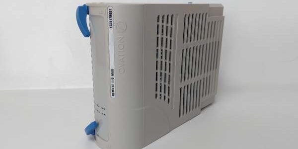
Product Core Brief
- Model: KJ3001X1-CA1 (cross PN: 12P1980X062)
- Brand: Emerson DeltaV
- Series: S-Series Traditional I/O Terminal Infrastructure
- Core Function: Keyed field wiring terminal base dedicated to 32-channel dry contact discrete input front cards
- Product Type: Plug-in rack-mounted I/O wiring carrier, screw-clamp field termination
- Key Specs: 32 DI circuit terminals | rotary mechanical key lock | 0.5–2.5mm² wire capacity | bussed 24VDC field wetting distribution
- Note: New original surplus unit; exclusively paired with VE4001S2T2B4 DI front module, incompatible with M-series rack hardware
Key Technical Specifications
| Parameter | Value |
|---|---|
| Supported Front Card | VE4001S2T2B4 32-channel dry contact DI module |
| Field Termination Style | M3 anti-loose screw clamp terminals |
| Acceptable Wire Gauge | 0.5–2.5 mm² solid/stranded copper wire |
| Mechanical Keying | Rotary lock key to prevent mismatched I/O card installation |
| Field Power Distribution | Bussed 24VDC wetting voltage distribution for dry contact loops |
| Mounting Platform | DeltaV S-Series DIN rail I/O carrier racks |
| Hot-Swap Compatibility | Front DI card supports hot-swap; base removal requires rack power shutdown |
| Operating Temperature | -40°C to +70°C operational; -40°C to +85°C storage |
| Environmental Grade | ISA S71.04 G3 corrosive gas resistant, PCB conformal coating |
| Vibration & Shock | 1mm pp (2–13.2Hz); 0.7g constant (13.2–150Hz); 10g half-sine 11ms shock |
| Physical Dimensions | 130mm W × 90mm H × 25mm D; net weight 0.30 kg |
| Hazardous Certifications | FM Class I Div2, ATEX Ex ec IIC Gc (Zone 2 cabinet installation only) |
| Enclosure Rating | IP20, restricted to indoor control cabinet mounting |
| Isolation Routing | Pass-through routing for 1500VAC opto-isolation circuits of paired DI front card |
Product Introduction
This wiring carrier acts as the fixed field termination interface for 32-point dry contact discrete input loops within DeltaV S-Series racks. It distributes shared 24VDC wetting power to valve limit switches, pump run relays and safety interlock contacts without extra auxiliary terminal blocks.Rotary mechanical keying eliminates accidental pairing with analog output or thermocouple front cards, a common source of backplane communication faults during rushed maintenance shifts. Screw-clamp terminals maintain consistent contact resistance under continuous cabinet vibration from plant fans and pump drives.
QA & Testing SOP
- Incoming Inspection: Cross-reference serial numbers against OEM factory batch logs; inspect terminal screw threads for galling and backplane edge connector gold plating for oxidation. Reject units with cracked plastic housing or broken key lock tabs.
- Mechanical Mating Test: Insert matching VE4001S2T2B4 front card 500 times to validate key lock engagement and consistent backplane contact resistance.
- Continuity & Bus Routing Test: Use Fluke 115 multimeter to verify unbroken signal paths between each field terminal and backplane edge pins; confirm no shorted terminal pairs.
- Keying Compatibility Check: Attempt insertion of mismatched AO/AI front cards to confirm mechanical lock blocks incompatible hardware seating.
- Final QC & Packaging: Blow PCB traces with dry nitrogen to remove industrial dust; seal unit in static-shield bag with printed test report capturing mechanical mating cycle data.
Installation Pitfalls & Guide
❗ ESD Component Failure Risk: Ungrounded contact with backplane traces damages bus signal routing circuits; full rack downtime labor costs exceed $2,500. Always attach a grounded anti-static wrist strap to cabinet safety ground before handling the base.❗ Zone 0/1 Hazardous Area Misapplication: The terminal base only holds Div2 safety certification. Deploying it in Zone 0 or Zone 1 flammable gas cabinets voids all safety approvals and creates ignition hazards.❗ M-Series Rack Cross-Installation: This hardware features incompatible pinout and mechanical form factor with M-series carriers; forced insertion permanently damages rack backplane gold pins.❗ Improper Wire Torque: Under-tightened screw terminals loosen over vibration, triggering intermittent open-circuit fault alarms; over-torquing strips terminal threads and fractures wire strands.❗ Live Base Removal Prohibition: The base carries shared bussed field power rails. Removing the unit while rack power stays energized cuts all 32 DI signals simultaneously and triggers full process interlock trips.
4-Step Replacement Guide
- Pre-install: Shut down upstream rack power supply and engage lockout/tagout; photograph all 32 field terminal wiring pin assignments for rebuild reference.
- Removal: Extract the paired VE4001S2T2B4 front DI card first; unclip DIN rail mounting latches and slide the empty base horizontally off the carrier rail.
- Install: Clip the new unit firmly onto S-Series DIN rail; set rotary mechanical key to match the DI front card profile; rewire each field contact per pre-install photos and torque screw terminals to OEM specified value. Reinsert the matching front DI card until key lock fully engages.
- Power-on Test: Restore rack power; cycle each field dry contact repeatedly and confirm all 32 discrete points report accurate status to the DeltaV HMI with no intermittent fault flags.
FAQ
Q: Can this base operate without the matching VE4001S2T2B4 front DI card?A: No, the base is purely a passive wiring carrier with no signal processing hardware; all input sensing and fault diagnostics reside on the paired front discrete input module.Q: Is hot-swapping allowed for this terminal base assembly?A: Hot-swap is only supported for the front DI card. The base itself must be removed with full rack power disconnected to avoid simultaneous loss of all 32 discrete input signals.Q: What fault patterns indicate a damaged terminal base?A: Multiple channels show permanent open-circuit faults with intact field wiring, consistent high contact resistance on screw terminals, inability to lock the paired front card via rotary key, or physical bending of backplane edge pins.Q: Can this terminal base accept active NPN/PNP proximity sensor wiring?A: It is engineered exclusively for passive dry contact loops with bussed 24VDC wetting power; active transistor-based sensors require a separate dedicated active DI terminal base variant.Q: What warranty coverage applies to new surplus stock?A: A 12-month limited warranty covers terminal housing, screw clamp hardware and backplane connector manufacturing defects. Damage from ESD mishandling, over-torqued wiring, forced insertion into M-series racks, or deployment in unapproved hazardous zones is excluded from coverage.Q: Does the rotary mechanical key lock prevent installation of non-DI front cards?A: Yes, each terminal base model has a unique key profile that physically blocks seating of mismatched analog output, analog input or FOUNDATION Fieldbus front modules to eliminate misconfiguration faults.




