
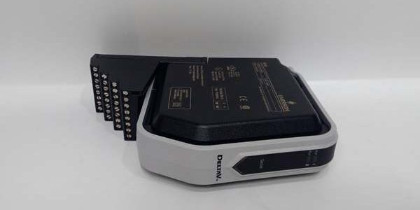
Product Core Brief
- Model: KJ1501X1-BC1 (cross reference PN 12P2186X022, VE5008)
- Brand: Emerson DeltaV
- Series: S-Series DCS Rack Power Infrastructure
- Core Function: DIN rail DC-DC converter that supplies regulated 12VDC LocalBus power to S-Series I/O carrier backplanes
- Product Type: Hot-swappable rack-mounted isolated system power module
- Key Specs: 24VDC field input | 12VDC @13A primary output | 5VDC auxiliary rail | built-in OR-ing for parallel redundancy
- Note: Discontinued OEM hardware; new surplus stock available, exclusive compatibility with DeltaV S-series I/O carriers
Key Technical Specifications
| Parameter | Value |
|---|---|
| DC Input Voltage | 24 VDC ±15% industrial cabinet supply |
| Primary LocalBus Output | 12 VDC, continuous 13 A max load capacity |
| Auxiliary Logic Rail | +5 VDC, 750 mA steady-state draw for backplane transceivers |
| Input-to-Output Isolation | 500 VAC galvanic isolation between 24V field and 12V backplane circuits |
| Redundancy Hardware | Integrated passive OR-ing diodes for dual parallel power pairing |
| Fault Protection | Overcurrent foldback, short-circuit auto-recovery, thermal shutdown |
| Hot-Swap Support | Safe live insertion/removal on energized safe zone cabinet racks |
| Operating Temperature | -40°C to +70°C operational; -40°C to +85°C storage |
| Environmental Grade | ISA S71.04 G3 corrosive gas resistant, full PCB conformal coating |
| Vibration & Shock | 1mm pp (2–13.2Hz); 0.7g constant (13.2–150Hz); 10g half-sine 11ms shock |
| Physical Dimensions | 120mm L × 50mm W × 150mm D; net weight 0.50 kg |
| Mounting Standard | 35mm standard DIN rail snap-in installation |
| Hazardous Certifications | FM Class I Div2, ATEX Ex ec IIC Gc (Zone 2 cabinet mounting only) |
| Compatibility Restriction | No mechanical or bus compatibility with DeltaV M-series I/O racks |
Product Introduction
This isolated DC-DC converter takes unregulated 24VDC cabinet power and conditions it into stable 12VDC LocalBus power for S-series I/O backplanes. The internal OR-ing diode circuit eliminates external redundancy modules when two of these units run in parallel for fault-tolerant rack power.Front-panel diagnostic LEDs display input presence, 12V output health, and thermal fault status for quick on-site troubleshooting. Per-channel foldback current limiting contains shorted backplane traces to avoid full rack power collapse during wiring faults.
QA & Testing SOP
- Incoming Inspection: Cross-reference serial numbers against OEM factory batch logs; inspect input terminal screw lugs for corrosion and PCB conformal coating for peeling. Reject units with cracked plastic housings or damaged DIN rail latches.
- Live Full-Load Testing: Mount on DIN rail, feed 24VDC input via Fluke 115 multimeter. Load the 12VDC rail to full 13A rated output for 24 hours; log voltage stability and surface thermal rise at steady state.
- Redundancy & Fault Stress Test: Pair two identical units to validate balanced load sharing; force short circuits on the 12V output rail to verify foldback limiting engages without permanent component damage.
- Status Indicator Verification: Confirm INPUT, POWER, and TEMP LEDs activate correctly under nominal, overload, and loss-of-input DC conditions.
- Final QC & Packaging: Purge PCB surfaces with dry nitrogen to remove industrial particulate contamination; seal unit in static-shield bag with printed test report capturing full-load runtime ripple and stability data.
Installation Pitfalls & Guide
❗ ESD Damage Risk: Ungrounded contact with internal power PCB traces destroys OR-ing diodes and switching MOSFETs; full rack shutdown labor costs exceed $2,600. Always attach a grounded anti-static wrist strap to cabinet safety ground before handling the module.❗ Cross-Series Rack Mismatch: This unit only interfaces with S-series I/O carriers. Forced mounting to M-series racks creates incompatible backplane voltage regulation and communication timeouts.❗ Zone 0/1 Hazardous Area Misuse: The power module holds only Div2 safety certification. Deploying it in Zone 0 or Zone 1 flammable gas cabinets voids all safety approvals and creates ignition hazards.❗ Mismatched Redundant Unit Revisions: Pairing hardware of different factory revisions creates unbalanced current draw, triggering premature thermal shutdown under peak I/O loading conditions. Match identical part revisions for redundant deployments.❗ Undersized 24VDC Input Feed Cables: Thin-gauge input wiring generates voltage drop under 13A peak load, triggering low-input fault alarms and unstable backplane voltage during high analog output card draw.
4-Step Replacement Guide
- Pre-install: Confirm the redundant standby power unit is active and carrying partial rack load; photograph 24VDC input terminal wiring for rebuild reference. Hot-swap is permitted in safe zone cabinets with redundant power configured.
- Removal: Toggle the unit’s front power slide switch to OFF; squeeze DIN rail mounting latches and slide the module horizontally off the rail without stressing input wiring lugs.
- Install: Clip the new unit firmly onto DIN rail; reconnect 24VDC input wiring per pre-install photos, torque terminal lugs to OEM specified torque value; slide front power switch to ON.
- Power-on Test: Monitor 12VDC LocalBus rail voltage via DeltaV diagnostic console for 2 continuous hours; simulate brief input power dropout to verify bumpless load transfer to the redundant standby module with zero I/O scan interruption.
FAQ
Q: Can a single unit power a full 8-slot S-series carrier loaded with mixed AI, DI, DO, and FF H1 cards?A: Only if total aggregate backplane current stays below the 13A limit. Racks with multiple analog output and FOUNDATION Fieldbus cards require dual redundant power units to avoid overload tripping during peak process transients.Q: Does hot-swapping the unit disrupt S-series I/O module operation?A: When paired with a second redundant power supply, load transfers seamlessly with no loss of 12VDC backplane voltage. Single-supply rack configurations require full rack power shutdown before removal.Q: What fault patterns signal a failed unit?A: Persistent red TEMP fault LED illumination at normal cabinet ambient temperatures, voltage sag under moderate 12V load, uneven load sharing when paired with a standby unit, or complete loss of 12VDC backplane output with valid 24VDC input present.Q: Can this module be mounted outside DeltaV S-series rack infrastructure as a standalone DC-DC converter?A: Not recommended. The backplane edge connector is engineered exclusively for S-series carrier bus pinouts; standalone wiring requires custom adapter hardware that voids OEM safety certifications.Q: What warranty coverage applies to new surplus stock?A: A 12-month limited warranty covers switching PCB, OR-ing diode circuit, and terminal hardware factory assembly defects. Damage from ESD mishandling, undersized input wiring voltage drop, overcurrent overload, forced installation into M-series racks, or deployment in unapproved hazardous zones is excluded from coverage.Q: Does the integrated OR-ing circuitry require external diodes for redundant parallel operation?A: No, passive OR-ing diodes are embedded on the PCB. Two matching units can be wired in parallel directly to the same 24VDC input bus without additional external redundancy hardware.




