
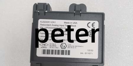
Product Core Brief
- Model: VE4033S2B1 (cross PN KJ3222X1-BA1, 12P2532X062)
- Brand: Emerson DeltaV
- Series: M-Series Traditional Rack I/O Series 2 Redundant I/O
- Core Function: 8-channel galvanically isolated redundant analog input card to acquire 4–20mA signals from HART smart pressure, flow and temperature transmitters for high-availability control loops
- Product Type: Plug-in rack-mounted redundant AI I/O module, mates with KJ4001X1-CA1 standard termination base
- Key Specs: 8 isolated channels | HART v7 transparent tunneling | 16-bit resolution | 1500VDC channel-to-system isolation | simplex/redundant rack pairing
- Note: New original surplus unit; physically incompatible with DeltaV S-series I/O carrier racks
Key Technical Specifications
| Parameter | Value |
|---|---|
| Channel Count | 8 independent galvanically isolated analog input channels |
| Standard Signal Span | 4–20mA; full measurement range 1–22.5mA overrange detection |
| D/A Conversion Resolution | 16-bit per channel |
| Channel Isolation Rating | 1500VDC optical isolation between field loop and LocalBus backplane |
| HART Support | HART v7 transparent pass-through for AMS device diagnostics and calibration |
| LocalBus Power Draw | 175mA typical simplex, max 250mA at 12VDC rack supply |
| Field Loop Drive | Regulated 24VDC wetting power, max 750Ω allowable transmitter load |
| Redundancy Operation | Dual-card hot standby with bumpless automatic failover on primary fault |
| Hot-Swap Compatibility | Safe live insertion/removal in energized safe zone I/O racks |
| Operating Temperature | -40°C to +70°C operational; -40°C to +85°C storage |
| Environmental Grade | ISA S71.04 G3 corrosive gas resistant, full PCB conformal coating |
| Physical Dimensions | 107mm W × 41mm H × 105mm D; net weight 0.30kg |
| Vibration & Shock | 1mm pp (2–13.2Hz); 0.7g constant (13.2–150Hz); 10g half-sine 11ms shock |
| Hazardous Certifications | FM Class I Div2, ATEX Ex ec IIC Gc (Zone 2 cabinet installation only) |
| Compatibility Restriction | Only fits M-series 8-slot I/O carriers, no S-series mechanical fit |
Product Introduction
This rack-mounted redundant analog input hardware collects 4–20mA process signals from field smart transmitters for critical DeltaV regulatory control loops. Per-channel optical isolation eliminates ground loop noise on long multi-conductor field cables routed near motor control centers.Built-in HART tunneling lets technicians pull device fault codes, calibration data and secondary process variables directly from the DCS workstation without handheld communicators. Dual-card standby redundancy eliminates single-point measurement failure risk for safety and revenue-critical plant loops.
QA & Testing SOP
- Incoming Inspection: Match serial numbers against OEM factory batch logs; inspect gold LocalBus edge connectors for oxidation and conformal coating for peeling. Reject units with cracked plastic housings or bent pin headers.
- Live Functional Testing: Install on matching M-series carrier, supply rack 12VDC LocalBus power via Fluke 115 multimeter. Feed precision 4–20mA signal sweep to each channel and validate consistent value reporting to DeltaV HMI.
- Isolation & Fault Stress Test: Run 1500VDC hipot isolation test between each channel and system ground (>100MΩ pass threshold); simulate wire short/open states to confirm open-loop fault alarms trigger correctly.
- Redundancy & Firmware Logging: Pair two identical units to validate bumpless failover during primary power cut; capture factory Series 2 firmware revision through DeltaV Diagnostic Console and save screenshots tied to the unit serial number for full traceability.
- Final QC & Packaging: Blow PCB surfaces with dry nitrogen to remove industrial dust; seal in static-shield bag with printed test report containing 24-hour continuous runtime stability data.
Installation Pitfalls & Guide
❗ ESD Component Failure: Ungrounded contact with backplane pins destroys analog front-end A/D chips; component replacement labor exceeds $2,300. Always attach a grounded anti-static wrist strap to cabinet safety ground before handling the card.❗ Cross-Series Carrier Mismatch: This hardware only seats on M-series racks. Forced insertion into S-series carriers bends backplane gold pins and disables full rack LocalBus communication.❗ Zone 0/1 Hazardous Area Misuse: The card holds only Div2 safety certification. Deploying it in Zone 0 or 1 flammable gas zones voids all safety approvals and creates ignition risks.❗ Mismatched Redundant Card Revisions: Pairing different firmware revisions for standby redundancy causes delayed failover and measurement drift during primary card fault conditions. Match identical hardware/firmware rev levels for redundant deployments.❗ Overloaded Field Loops: Transmitter load resistance above 750Ω drops loop voltage below the HART communication threshold, triggering intermittent device offline alarms during process transients.❗ EMI Wiring Separation Failure: Run 240VAC power cables a minimum 10cm apart from analog signal wiring. Parallel routing causes persistent analog value jitter and corrupted HART diagnostic data.
4-Step Replacement Guide
- Pre-install: Activate control loop bypass logic on the DeltaV workstation for all 8 associated field transmitter loops; photograph terminal block field wiring layout for reference. Hot-swap is permitted in safe zone cabinets.
- Removal: Release the card’s front retention latch, pull the unit straight outward horizontally to avoid bending backplane edge pins. For redundant racks, leave the standby card powered to maintain measurement coverage during swap.
- Install: Align the new module’s gold backplane connector with the carrier slot, push fully until the retention latch clicks into locked position. Confirm mechanical key matches CA1 termination block profile.
- Power-on Test: Clear all loop bypasses; sweep 4mA, 12mA, and 20mA reference signals to validate stable analog readings, then pull HART device diagnostic data to confirm unbroken field communication. Simulate primary card fault to verify seamless redundant failover.
FAQ
Q: Can each channel power standard 2-wire HART transmitters?A: Yes, the internal 24VDC loop supply delivers minimum 15VDC at 20mA output, compatible with all industry standard 2-wire smart transmitters within the 750Ω maximum load limit.Q: Does hot-swapping the card disrupt other I/O modules on the same carrier rack?A: The M-series carrier includes buffered hot-swap circuitry; removing or inserting the unit while rack power stays energized will not interrupt signal processing for other installed I/O cards. In redundant rack layouts, the standby card maintains full measurement data during primary card replacement.Q: What physical limitation blocks use with S-series DeltaV racks?A: M-series and S-series carriers use incompatible backplane pinout geometries and LocalBus signaling timings; forced installation permanently damages the carrier’s backplane connector pins.Q: What hardware behavior signals a failed unit?A: One or multiple channels report constant full-scale or zero values, persistent open-loop fault flags on healthy field wiring, full LocalBus communication timeout on the carrier rack, missing front-panel channel status LED indicators, or failed redundant failover during primary card power loss.Q: What warranty coverage applies to new surplus stock?A: A 12-month limited warranty covers factory PCB and assembly defects. Damage from ESD mishandling, overloaded field loops, field-side overvoltage, mismatched redundant firmware revisions, or deployment in unapproved hazardous zones is excluded from coverage.Q: Can multiple HART transmitters wire in parallel on a single channel?A: No, parallel instruments increase total loop resistance and pull supply voltage below HART operating limits, creating intermittent device disconnection and lost diagnostic data.




