
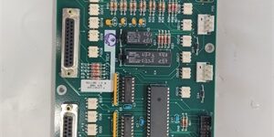
Product Core Brief
- Model: 0100-71229
- Brand: Applied Materials (AMAT)
- Series: Centura Air-Cooled Mid-High Power Main RF Generator Spare Hardware Line
- Core Function: Delivers stabilized 13.56MHz RF power to vacuum process chambers; closed-loop power regulation offsets variable plasma impedance to maintain consistent thin-film deposition and etch uniformity during full wafer batch runs
- Product Type: Air-cooled solid-state main RF power generator module
- Key Specs: Fixed 13.56MHz operating frequency | 2000W continuous RF rating | Air-air forced air cooling | Analog + RS232 signal & communication
- Note: New OEM OEM spare; factory-matched RF match assemblies for 4000/3000W+ power tier available for system-level integration.
Key Technical Specifications
- Operating Frequency: Fixed 13.56 MHz standard RF plasma band
- Max Continuous RF Output Power: 2000 W continuous, 3000W peak pulse mode
- Nominal System Impedance: 50 Ω factory calibrated to match AMAT Centura RF matching networks
- Power Regulation Accuracy: ±0.5 W steady-state closed-loop forward power stability
- Cooling System: Integrated low-noise axial fan forced air convection with disposable intake particle filter
- RF Output Interface: 7/16 DIN high-power coaxial port
- Control Signals: 0–10 V analog power setpoint / reflected power feedback; RS232 serial host tool communication
- Built-In Protection Interlocks: Over-reflected power trip, over-temperature shutdown, over-current protection, hardware safety interlock inhibit
- Enclosure Rating: IP30 low-outgassing sealed cabinet, compliant with Class 1 cleanroom particulate limits
- Operating Ambient: 18°C–26°C cleanroom temperature, 30–70% non-condensing relative humidity
- Safety & EMC Compliance: SEMI S2, CE industrial equipment certification
- Net Unit Weight: 6.1 kg
- Outer Overall Dimensions: 256 mm W × 315 mm H × 172 mm D
Product Introduction
This air-cooled 2000W main RF generator is the primary plasma energy source for medium-heavy load AMAT Centura PVD and dielectric etch chambers. Real-time closed-loop power correction automatically compensates for plasma impedance drift induced by showerhead coating, wafer surface charging, and gas flow fluctuation to eliminate cross-wafer thickness non-uniformity across full production lots.Air-cooled architecture eliminates facility DI water cooling piping, reducing rack infrastructure cost and simplifying multi-chamber compact cluster tool layout. Multi-stage fault interlocks execute controlled power cutoffs to minimize wafer scrap and extend service life of downstream RF match assemblies and vacuum chamber hardware.
QA & Testing SOP (Transparency Building)
- Incoming Inspection: Cross-reference AMAT OEM serial database to validate genuine cleanroom-grade hardware; inspect 7/16 DIN RF port center pins, cooling fan blade integrity, and control terminal blocks for corrosion, bending or surface scratches.
- Live Testing: Couple the unit to calibrated 13.56MHz high-power dummy RF load; supply stabilized 208VAC input power via Fluke calibrated bench source; run 24-hour cyclic load testing at 1600W fixed setpoint, log forward/reflected power drift and thermal fan runtime every hour.
- RF Electrical Calibration Test: Network analyzer frequency sweep range 10–15MHz; pass threshold <0.4% reflected power at nominal 13.56MHz operating frequency.
- Firmware & Config Backup: Record factory PID power loop tuning parameters stored on onboard flash memory; photograph analog and serial control wiring pinout layout for direct one-to-one replacement matching.
- Final QC & Packaging: Purge internal air cavities with dry nitrogen to remove manufacturing residual particulates; seal inside double-layer anti-static vacuum packaging; attach printed test tag with serial trace number and full RF stability test records.
Installation Pitfalls & Guide (Engineer to Engineer)
❗ Frequency Mismatch Hazard: This hardware only supports 13.56MHz main RF matching networks. Mating with 400kHz low-frequency bias match assemblies generates extreme reflected power and immediate interlock trips.❗ Incorrect RF Connector Torque: Under-tightened 7/16 DIN fittings create impedance discontinuities; over-torquing cracks internal PTFE insulation leading to permanent RF leakage. Strictly follow OEM 12 N·m torque specification.❗ Unfiltered Cooling Air Intake: Unprocessed cleanroom air pulls fine dust onto internal power semiconductors and PCB traces, triggering recurring over-temperature trips within 2–3 months of continuous production. Install OEM 0.01μm intake particle filter.❗ EMI Cross-Routing Risk: Running low-voltage analog/RS232 control cables parallel to 208VAC main power wiring induces electrical noise, causing random power setpoint jumps that distort wafer process uniformity. Separate cable trays with minimum 15cm vertical clearance.❗ Unmitigated RF Safety Exposure: Ungrounded service technicians face high-frequency RF burn hazards during live cabinet maintenance; wear RF-rated insulated gloves and grounded anti-static wristbands before opening powered enclosure panels.
4-Step Replacement Guide
- Pre-install: Complete lockout/tagout of tool AC facility power and RF generator supply; photograph RF coax routing, analog serial control pin assignments, and air filter mounting position for exact configuration replication.
- Removal: Disconnect high-power 7/16 DIN RF cable; unplug analog and RS232 control harness; remove four rack mounting fasteners and extract the unit from chamber rack slots.
- Install: Secure new unit to rack with OEM specified torque values; reattach RF coax tightened to 12 N·m; reconnect all control wiring matching photographed pin layout; mount brand new OEM air intake filter.
- Power-on Test: Restore facility 208VAC AC supply; execute factory auto power calibration routine; verify reflected power remains below 0.4% across full process impedance window before releasing wafer production batches.
FAQ (Frequently Asked Questions)
Q: Can this generator sustain continuous 2000W full-power 24-hour production shifts?A: Yes, with filtered intake air and stable 18°C–26°C cleanroom ambient. Sustained full-power operation above 26°C ambient triggers thermal power derating.Q: Does this RF module support hot-swap while the Centura cluster tool stays energized?A: No. Live disconnection of AC input and RF lines generates dangerous voltage transients, damages internal RF amplifier semiconductors, and poses severe RF burn safety hazards. Full lockout/tagout procedure is mandatory.Q: What triggers repeated high reflected power faults after unit replacement?A: Primary root causes include mis-torqued RF coaxial connectors, clogged air intake filters, or chamber showerhead deposition shifting plasma load impedance outside the RF match tuning range.Q: Are third-party generic RF generators drop-in interchangeable with this OEM unit?A: Physical rack dimensions may align, but non-OEM hardware lacks proprietary AMAT power control firmware optimized for Centura plasma profiles, leading to uncorrectable wafer thickness non-uniformity.Q: What OEM preventive maintenance interval applies to internal fan and PCB assemblies?A: 12 months of continuous 24/7 production with filtered intake air; fabrication facilities with elevated cleanroom particle levels require bi-annual fan and filter replacement to avoid thermal fault trips.Q: Can this RF source integrate with non-AMAT third-party vacuum processing chambers?A: It physically interfaces via standard 50Ω RF ports, but proprietary analog interlock and serial communication protocols only natively interface with AMAT Centura platform control systems.Q: What warranty coverage applies to surplus OEM spare generator units?A: Standard 12-month functional warranty covers oscillator, power amplifier and control circuit manufacturing defects; damage from unfiltered cooling dust ingress, improper RF connector torque, or live RF service mishandling is fully excluded from coverage.





