
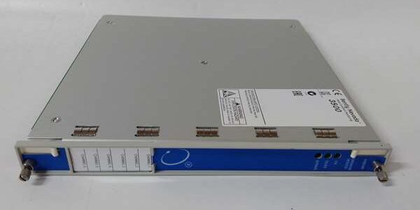
Product Core Brief
- Model: 3500/50 (Front Card PN 286566-02), matched rear terminal base PN 128240-01
- Brand: Bently Nevada (Baker Hughes)
- Series: 3500 Machinery Protection TSI Rack System
- Core Function: Dual-channel tachometer monitor that processes dual independent Keyphasor/magnetic pickup pulse signals for RPM, zero-speed, rotation direction and synchronous vibration tracking
- Product Type: Single-slot hot-swappable split front/rear base dual speed measurement M-series card
- Key Specs: 2 isolated pulse input channels | Max 20 kHz pulse frequency | 7.2W typical power draw
- Note: Active OEM production hardware; factory-new and refurbished surplus stock available, enables dual redundant shaft speed sensing without occupying two separate rack slots.
Key Technical Specifications
- Dual independent differential pulse input channels, exclusive pairing with rear I/O base 128240-01
- Supported transducers: 3300 XL proximity Keyphasor probes, variable reluctance magnetic speed pickups
- Input signal range: -24 VDC to +10 VDC differential pulse, 20 kΩ per-channel input impedance
- Pulse frequency limit: 0–20 kHz, full RPM measurement span 0–99,999 RPM
- Speed reading accuracy: ±0.01% full scale above 10,000 RPM; ±0.1 RPM below 10,000 RPM
- Built-in measurement logic: RPM value, zero-speed detection, forward/reverse rotation direction flag
- Analog recorder output: Isolated 4–20 mA per channel proportional RPM signal, 550 Ω max load resistance
- Power consumption: 7.2 W typical continuous draw from rack 24 VDC backplane bus
- Galvanic isolation: 1500 VAC channel-to-backplane isolation, per-input TVS surge suppression
- Operating temperature: -30°C to +65°C standard; conformal coated variant rated -40°C to +85°C offshore cabinet deployment
- Alarm logic: Per-channel configurable Alert/Danger speed thresholds, supports TMR 2oo3 redundant rack voting
- Physical weight: 0.78 kg single slot form factor, fully hot-swap compatible without full rack de-energization
- Compliance certifications: API 670, CE EMC, UL Class I Div 2, ATEX Zone 2 hazardous cabinet rated
Product Introduction
This dual-channel tachometer eliminates the need for two separate single-channel speed cards to implement redundant shaft speed monitoring on turbines and compressors. It conditions two independent pulse signals and distributes calibrated RPM data to the rack backplane for vibration synchronous tracking and DCS trending.Its primary field value is slot conservation. Dual-channel hardware cuts rack slot usage in half for redundant speed sensing layouts, while the split rear base design allows wiring rework without extracting the front measurement card during maintenance windows.
QA & Testing SOP (Transparency Building)
- Incoming Inspection: Cross-reference serial numbers against OEM M-series production databases to reject counterfeit hardware. Complete physical audit of PCB traces, front buffered BNC ports, rear base screw terminals, and front panel status LEDs; timestamp photos of connector corrosion or pin deformation.
- Live Power-On Testing: Mount the front card and matched rear base into a calibrated test 3500 rack powered by a Fluke 115 24VDC supply. Execute a continuous 24-hour load test with dual-channel variable frequency pulse simulation to validate stable power draw and consistent backplane data polling to the Slot1 TDI.
- Electrical Isolation Testing: Use a megohmmeter to confirm insulation resistance >10 MΩ between all speed signal terminals and rack protective ground; verify zero leakage current across isolation barriers during full pulse swing simulation.
- Firmware & Config Backup: Flash the latest OEM M-series compatible firmware revision, log exact version numbers, and archive a blank dual-channel speed configuration file to offline storage. Record baseline LED behavior during zero-speed and overspeed threshold trigger simulation for post-replacement fault comparison.
- Final QC & Packaging: Inject calibrated pulse frequencies across full RPM operating range on both channels to validate linear 4–20 mA recorder output scaling. Separate front card and rear base into anti-static foam inserts, attach serialized QC test tag with full test timestamp, and seal inside ESD shielding packaging for transit.
Installation Pitfalls & Guide (Engineer to Engineer)
❗ Firmware Rev Mismatch Risk: Mismatched rack-wide M-series firmware revisions trigger permanent TX/RX communication faults and disable dual-channel redundant speed voting logic. Export the full rack firmware stack before swapping the module; never deploy mixed legacy/M-series firmware sets across rack slots.❗ Rear Terminal Base Mismatch Risk: Pairing the front card with any I/O base other than 128240-01 breaks dual-channel transducer wiring pinouts and removes built-in channel surge suppression, creating erratic RPM readings and false speed fault alarms.❗ Dual-End Ground Loop Wiring Risk: Grounding Keyphasor coaxial cable shielding at both the rear terminal base and machinery junction boxes creates circulating ground loop current that distorts pulse waveform integrity, triggering random nuisance speed fault flags during turbine startup VFD transients.❗ ESD Damage Risk: Ungrounded field tools discharge static through front BNC signal ports or exposed rear base terminal pins, destroying pulse conditioning ADC front-end circuits; OEM PCB repair costs exceed $1,600 for production M-series hardware.❗ Missing Dual-Channel Speed Setpoint Backup Risk: Failing to export validated Alert/Danger RPM threshold values for both channels prior to replacement resets all redundant speed protection limits to factory defaults, removing cross-channel fault detection capability for rotating machinery.
4-Step Replacement Guide
- Pre-install: Attach ESD wrist strap, photograph rear terminal dual Keyphasor wiring layout, export full rack dual-speed TMR voting configuration, and record active rack firmware revision set. Capture front LED channel status baseline for post-swap validation.
- Removal: Unlatch front panel lock levers to disengage backplane pins, slide the front card straight out of its assigned rack slot without bending PCB edge connectors; disconnect the matched 128240-01 rear base wiring harness and unmount the base from rack rear rails.
- Install: Mount the matching 128240-01 rear terminal base first on rack rear rails, align the replacement front card’s backplane pins with the rack bus, slide fully into the slot, squeeze extraction levers to lock contact pins, and re-terminate dual Keyphasor/magnetic pickup wiring strictly matching the photographed terminal layout.
- Power-on Test: Restore rack power, upload saved dual-speed rack configuration, inject calibrated pulse test signals across full RPM range on both channels, validate linear 4–20mA DCS trending, cross-channel speed deviation fault detection and functional Alert/Danger alarm state triggers before returning the turbine/compressor to automatic operation.
FAQ (Frequently Asked Questions)
Q: Does this unit support live hot-swap operation with the rack energized?A: Yes, the front measurement card is rated for hot-swap without full rack power loss. Hardwired speed alarm relay trip logic remains active during removal and replacement, so machinery speed-related protection interlocks do not drop out mid-swap. The rear terminal base cannot be removed while energized.
Q: Can this assembly replace two single-channel 3500/53M cards for redundant speed monitoring?A: Yes, it consolidates two independent speed inputs into one rack slot, reducing slot consumption by half. All redundant speed comparison and cross-channel fault detection logic is natively supported via rack configuration software.
Q: What warranty coverage applies to refurbished surplus inventory?A: Refurbished stock carries a 12-month functional warranty covering PCB pulse conditioning, backplane communication, analog output, and channel fault detection circuits; cosmetic scratches and terminal screw wear are excluded from claims. Factory-new OEM units ship with a full 36-month manufacturer warranty.
Q: Will rack power cycling erase stored dual-channel speed threshold and voting configurations?A: No. All RPM trip limits, pulse count scaling, and cross-channel deviation logic parameters write to non-volatile onboard flash memory; power loss or full rack shutdown does not clear saved speed measurement configuration data.
Q: Does this module independently store transient speed pulse waveform snapshots on its own PCB?A: No. High-resolution post-fault pulse waveform capture functionality is managed exclusively by the rack’s Slot1 TDI master module; this hardware only processes steady-state RPM measurements and speed threshold alarm logic.
Q: Can proximity probes and magnetic pickups be mixed across its two input channels?A: Yes. Each channel is independently configurable to accept either proximity Keyphasor or variable reluctance magnetic pickup signals without cross-channel signal interference.
Q: What happens if one speed channel suffers an open or shorted transducer fault?A: The faulty channel triggers a front-panel OK LED fault state and logs the error to rack memory. The second fully functional channel continues normal RPM measurement, and cross-channel deviation alarms activate to alert operators of single-probe loss without full loss of speed monitoring.





