
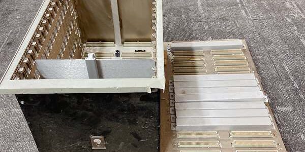
Product Core Brief
- Model: 3500/05-01-03-00-00-00
- Brand: Bently Nevada (Baker Hughes)
- Series: 3500 Machinery Protection TSI Rack System
- Suffix Breakdown:01 = Full-size 14-slot rack; 03 = Bulkhead flush panel mounting; 00 = No hazardous agency approvals; 00 = Reserved blank field; 00 = No dedicated EU compliance marking
- Core Function: Passive mechanical chassis with integrated backplane bus that physically mounts and electrically interconnects all 3500 series monitor, communication, and power supply modules
- Product Type: Full-size 14-slot bulkhead-mount TSI system rack (passive backplane, no internal power conversion)
- Key Specs: 14 standard single module slots | Bulkhead panel cutout mounting | Passive convection cooling
- Note: Active OEM production mechanical rack; factory-new and refurbished surplus inventory available; requires separate 3500/15 power supply modules for backplane power distribution.
Key Technical Specifications
- Slot layout: 14 single-width module slots, Slot 1 reserved exclusively for TDI rack master module
- Mounting form: Bulkhead flush panel mount; dedicated cutout dimensions for cabinet front panel installation
- Backplane architecture: Passive multi-layer copper bus with isolated signal and power traces for all rack slots
- Supported modules: All M-series and legacy single-slot 3500 monitor, comm, and power supply cards
- Power slot allocation: Left two half-height slots dedicated to dual redundant 3500/15 power supply modules
- Cooling method: Passive natural convection; no integrated rack fans, requires minimum 50mm clearance top/bottom
- Operating ambient range: -30°C to +65°C standard cabinet; conformal coated backplane variant rated -40°C to +85°C
- Physical dimensions: 482.6mm W × 274.3mm H × 266.7mm D; total chassis weight 6.3kg empty
- Backplane isolation: 1500VAC separation between power distribution rails and signal bus traces
- Maximum full rack load capacity: Supports full 14-slot populated chassis with dual redundant 3500/15 power supplies
- Certifications: Base CE general EMC compliance; suffix 00 removes Class I Div 2 / ATEX Zone 2 hazardous approvals
- Mechanical rating: IP20 front panel protection against finger contact with live backplane pins
Product Introduction
This full-size 14-slot bulkhead rack acts as the mechanical and electrical foundation for complete rotating machinery TSI protection systems. Its passive backplane creates a shared communication and power bus that links every inserted monitor card without external wiring jumpers.Its primary field design benefit is bulkhead flush mounting. The chassis installs flat against cabinet front panels to eliminate protruding rack hardware, ideal for compact MCC and turbine local control panels with limited depth clearance.
QA & Testing SOP (Transparency Building)
- Incoming Inspection: Cross-reference serial numbers against OEM rack production logs to screen counterfeit frames. Complete physical audit of backplane gold contact pins, slot guide rails, bulkhead mounting flanges, and ground bus terminals; timestamp photos of bent rails, tarnished pins, or chassis corrosion.
- Live Backplane Continuity Testing: Load the chassis with calibrated test power supply and dummy monitor cards for continuous 24-hour continuity test. Verify zero open-circuit or short-circuit faults across all backplane signal and power traces under full thermal load cycling.
- Isolation Integrity Testing: Use a megohmmeter to confirm insulation resistance >10 MΩ between all power rails and signal bus traces; validate no leakage current across backplane isolation boundaries.
- Mechanical Fit Check: Insert and extract all compatible single-slot modules 50 times to confirm smooth hot-swap operation without pin scuffing or rail binding; verify bulkhead flange mounting hole alignment matches OEM cutout drawings.
- Final QC & Packaging: Perform full backplane continuity scan one final time, attach serialized QC test tag with timestamped continuity report, wrap chassis in anti-static bubble wrap and ship inside rigid plywood crate to prevent rail bending during transit.
Installation Pitfalls & Guide (Engineer to Engineer)
❗ Backplane Pin Contamination Risk: Dust, metal shavings, or cabinet condensation on backplane gold pins creates intermittent communication dropouts across all rack modules. Never remove front module blanking plates for long-term unpopulated slots.❗ Mounting Flange Misalignment Risk: Over-torquing bulkhead mounting fasteners warps the chassis frame, bending backplane edge connectors and causing permanent module hot-swap contact faults. Follow OEM torque specification of 2.2 N·m maximum per mounting bolt.❗ Single Power Supply Operation Oversight: Running the rack with only one 3500/15 power supply creates single-point power failure risk; API 670 turbine and compressor safety racks require dual redundant power supplies in the left dedicated slots.❗ Insufficient Clearance Thermal Risk: Mounting the rack with less than 50mm vertical clearance blocks passive convection cooling, raising backplane operating temperature above rated limits and accelerating PCB component degradation in inserted monitor cards.❗ ESD Backplane Damage Risk: Ungrounded field tools touching exposed backplane pins during module installation discharge static, destroying delicate signal bus trace circuitry; replacement backplane repair costs exceed $2,200 for full chassis rework.
4-Step Replacement Guide
- Pre-install: Attach ESD wrist strap, power down all rack power supplies and isolate facility AC/DC feed, photograph full rack module slot layout and power supply wiring, record all module serial numbers and slot positions for post-migration reinsertion.
- Removal: Extract every monitor, communication, and power supply module sequentially and store each unit in labeled anti-static foam. Remove all bulkhead mounting bolts and slide the empty chassis out of the cabinet cutout.
- Install: Align the new chassis bulkhead flange to the cabinet cutout, torque mounting bolts to 2.2 N·m evenly across all flange holes to avoid frame warping. Reinstall dual redundant 3500/15 power supplies in the left two half-height slots first, then reinsert all monitor cards matching pre-swap slot layout photos.
- Power-on Test: Restore facility power to both redundant power supplies, confirm front panel OK LEDs on all inserted modules, execute full backplane scan via Slot1 TDI master module, verify unbroken DCS tag communication and no backplane fault alarms before returning machinery to automatic operation.
FAQ (Frequently Asked Questions)
Q: Does this chassis support hot-swap of individual monitor modules while the rack remains energized?A: Yes, all single-slot M-series and legacy monitor cards are rated for hot-swap with the rack powered. The passive backplane maintains isolated power and signal rails for remaining active modules during card extraction.
Q: Can this bulkhead rack be converted to 19-inch EIA rail mounting after installation?A: No direct conversion possible. The suffix -03 bulkhead flange is permanently integrated to the chassis frame; EIA rack-mount variants carry different suffix codes and use separate side mounting brackets incompatible with this unit.
Q: What warranty coverage applies to refurbished surplus rack chassis inventory?A: Refurbished empty racks carry a 12-month functional warranty covering backplane continuity, slot rails, and mounting flange integrity; cosmetic dents, minor paint wear, and surface scuffs are excluded from claims. Factory-new OEM chassis ship with a full 36-month manufacturer warranty.
Q: Will mixing legacy non-M and M-series monitor cards in the same rack cause backplane communication faults?A: No backplane hardware conflict occurs, but rack-wide firmware must be unified to a compatible cross-generation revision set; mismatched firmware versions will trigger persistent TX/RX communication errors on mixed slot modules.
Q: Does this rack include built-in power conversion circuitry to supply 24VDC to the backplane bus?A: No. The chassis is a passive mechanical backplane only. Two separate 3500/15 power supply modules must be installed in the left half-height slots to convert facility AC/DC input to regulated rack backplane power.
Q: Can the 3500/05 mini seven-slot modules be installed into this full-size 14-slot chassis?A: No physical compatibility. Mini-rack half-height modules use different edge connector pinouts and form factors that cannot seat into standard full-size rack slot guides.
Q: What happens if one redundant 3500/15 power supply fails mid-operation?A: The second active power supply automatically carries the full rack load without interruption to backplane voltage or module operation. A fault status flag logs to the Slot1 TDI module for DCS alarming and maintenance tracking.





