
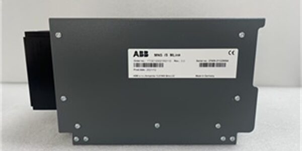
Component Snapshot
- Model: 1TGE120021R0110
- Manufacturer: ABB
- Product Line: MNS iS 3.0 Intelligent Low-Voltage Switchgear Protection & Control Unit
- Hardware Type: Integrated intelligent motor protection relay / multi-function feeder protection controller
- Core Key Features:
- Full motor protection: overload, locked rotor, short-circuit, earth leakage, phase loss, phase unbalance, over/under voltage
- Built-in dual Ethernet (Modbus TCP) for redundant plant communication
- Local LCD display + multi-color status LED for real-time current, voltage, power, fault recording
- Dual-channel safety input (emergency stop, safety door) with SIL3 / PLe functional safety certification
- Onboard digital DI/DO for motor starter interlock control
- Configurable trip curves, event sequence-of-fault (SOE) storage
- Typical Application: Protection and monitoring of three-phase asynchronous motors, small feeders in power plant auxiliary systems, refinery pump/compressor control cabinets, chemical plant MNS low-voltage switchgear, water treatment motor control centers (MCC)
Hard-Numbers Technical Specifications
Power Supply
- Rated control voltage: 24VDC wide range, operating input 19.2–30VDC
- Nominal power consumption: 5W, max 7.2W under full communication load
- Anti-reverse, overvoltage & surge protection built-in
Electrical Measurement & Protection Ranges
- Supported CT secondary current: 1/5A selectable, motor rated current 0.1–630A scalable
- Protection functions & thresholds:
- Overload: Class 5/10/15/30 inverse time trip curve adjustable
- Short-circuit: Instantaneous or definite-time delay trip
- Earth fault leakage: 0.03–5A adjustable
- Phase loss / phase unbalance: 5–40% unbalance threshold
- Overvoltage / undervoltage: ±10% rated line voltage trip window
- Sampling cycle: 20ms real-time three-phase current/voltage acquisition
Communication Interfaces
- Dual independent RJ45 Ethernet ports (LAN1 / LAN2) 10/100Mbps auto-negotiate
- Supported protocol: Modbus TCP, IEC 60870-5-104 optional firmware
- Redundant network failover within <100ms; integrated web server for local parameter configuration
Digital I/O Channels
- Digital Inputs (DI): 8 channels, 24VDC sink/source compatible (for local start/stop, fault feedback, safety interlock)
- Digital Outputs (DO): 6 relay contact outputs, 5A@250VAC resistive load (trip, alarm, starter interlock)
- Dual safety DI channel certified for SIL3 safety circuits (IEC 61508)
Environmental & Mechanical
- Operating temperature: -20°C ~ +70°C full protection accuracy; storage -40°C ~ +85°C
- Humidity: 5%–95% RH non-condensing, anti-condensation PCB coating
- Isolation rating: 2000VAC reinforced isolation between CT measurement circuits, communication bus and control power
- Mounting: Standard 35mm DIN rail lock mounting, IP40 front panel protection
- Physical dimension: 144mm (H) × 90mm (W) × 65mm (D); unit weight ~0.52kg
- PCB Treatment: Factory acrylic conformal coating for oily, dusty industrial MCC cabinet environments
- Certifications: CE, UL, IEC 60947-1, IEC 60947-4-1, SIL3, ATEX Zone 2, Class I Div 2 non-incendive
Diagnostic & Data Storage
- Front panel multi-color LED: Power, Run, Alarm, Trip, LAN Link/Activity
- Built-in LCD: Displays three-phase current, voltage, power factor, energy, fault codes
- Non-volatile flash memory: Stores up to 1000 SOE fault records, parameter sets retained after full power loss
- Hardware self-test on power-up: CT open circuit, communication port, relay contact integrity check
System Pain Points Solved
- Consolidate multi-device functions into single unitSeparate thermal overload relays, separate current meters, separate Modbus communication modules and safety interlock relays waste multiple DIN rail slots. This integrated unit combines measurement, full motor protection, local display and dual redundant communication to cut cabinet hardware count and wiring labor.
- Dual Ethernet eliminates single communication failure riskSingle-port protection relays lose all motor operating data and fault alarms if one network cable fails; dual LAN ports enable automatic active/standby switchover to ensure uninterrupted data upload to plant DCS/800xA SCADA.
- SIL3 safety dual-input design meets process safety audit standardsOrdinary motor relays lack certified safety channel, cannot be used for emergency stop and safety door interlock circuits of refinery compressors and high-risk production lines; built-in SIL3 safety DI removes external safety relay hardware cost.
- Conformal coating adapts to harsh power plant/refinery MCC cabinetsUncoated protection relays suffer measurement drift, random false overload trips from condensed oil mist and humidity; full coated PCB stabilizes measurement precision long-term.
- Onboard SOE fault logging simplifies post-fault root cause analysisDiscrete thermal relays cannot record fault time stamp and pre-fault operating parameters; internal fault event storage provides complete sequence data for maintenance troubleshooting without extra data loggers.
Internal Hardware Architecture & Working Principle
This intelligent protection unit integrates independent measurement ASIC, safety logic processor and dual Ethernet communication controller; all motor protection judgment logic runs on hardware with fixed deterministic response time, independent of upper-level DCS communication status.
- 24VDC DIN rail input feeds multi-stage isolated power regulators for measurement circuit, LCD display, dual Ethernet transceivers and relay drive circuits.
- Three-phase CT secondary current signals enter isolated measurement ASIC via terminal blocks; real-time sampling calculates current unbalance, overload, leakage and short-circuit values, compares with user-configured trip thresholds.
- Dual SIL3 safety DI channels execute hardware cross-monitoring of emergency stop/safety door signals; any safety loop fault triggers immediate trip output without software delay.
- Dual LAN Ethernet ports operate redundant mode; motor running data, fault codes and SOE records transmit to plant SCADA via Modbus TCP; web server supports local laptop parameter modification without engineering software.
- 6-channel relay DO outputs execute trip, alarm and motor starter interlock commands; each relay equipped with TVS surge suppression to absorb inductive load kickback.
- Front LCD and tri-color LED deliver local on-site visual status without connecting HMI; all protection curve parameters and fault records store in non-volatile flash memory.
- Full acrylic conformal coating encapsulates PCB traces, semiconductors and solder joints to prevent leakage current and intermittent measurement faults from cabinet oil mist and condensation.
Common Field Service Mistakes & Compliance Rules
1. CT secondary circuit open-circuit without pre-power-off check
Hazard: Live CT open circuit generates thousands of volt high potential, damaging the 1TGE120021R0110 measurement ASIC and creating electric shock risk for technicians.Rule: Fully de-energize upstream motor feeder breaker before disconnecting or replacing CT wiring; short-circuit CT secondary terminals with shorting bar during maintenance.
2. Dual-end grounding of CT / Ethernet cable shielding
Hazard: Parallel ground loop AC noise distorts three-phase current sampling values, triggering false overload or earth fault trip alarms during VFD pump/compressor operation.Rule: Terminate all CT signal cable and Ethernet cable shield braids only at the MCC cabinet chassis ground bar; fully tape and isolate shield conductors at remote motor junction boxes and switch rooms.
3. Mismatched firmware after unit replacement
Hazard: Outdated firmware between protection unit and plant SCADA Modbus master causes tag offset, missing fault data and communication intermittent dropout.Rule: Upload matched firmware version consistent with DCS system configuration; run full Modbus point scan and motor trip functional test before restoring motor operation.
4. Insufficient cabinet ventilation causing thermal drift
Hazard: Stacking multiple 1TGE120021R0110 units without vertical clearance blocks convection cooling; internal PCB temperature exceeds +70°C rated limit, leading to trip curve offset and random false alarms.Rule: Reserve minimum 50mm vertical empty space above and below each unit; clean cabinet air filter every 90 days for oily refinery and power plant auxiliary MCC rooms.
5. Improper relay output terminal torque
Hazard: Over-tightening crushes thin wire strands; under-tightening creates high-resistance loose contacts that disconnect under cabinet vibration, leading to failure of motor trip/alarm output.Rule: Torque DO terminal block screws to ABB standard 0.6 N·m; re-torque all field wiring terminals during quarterly MCC cabinet inspection cycles.
Commercial Availability Note
Please note: All above technical content is for engineering and maintenance reference only and does not constitute binding quotation terms. Final unit price, factory lead time, warranty scope and bulk order discounts shall be negotiated based on inventory availability, project order quantity and site delivery schedule.




