
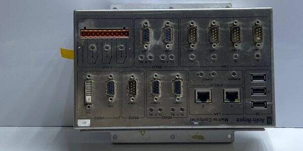
Component Snapshot At-a-Glance
- Model: H1111.0103
- Alt. P/N: Factory part number 75669; sibling variants H1111.0203 / H1111.0204
- Product Series: Rolls-Royce Marine Propulsion & Auxiliary Engine Control Platform
- Hardware Type: Standalone rugged marine main control unit (MCU) with integrated multi-protocol communication gateway
- Key Feature: Dual redundant LAN Ethernet + multi-channel CAN bus + serial RS232/422/485 ports, vibration-resistant stainless steel chassis, PIC firmware V2.2 native
- Primary Field Use: Closed-loop control of marine main propulsion engines, shaft generators, thrusters and auxiliary diesel gensets; execute safety overspeed, lube oil low-pressure and fire shutdown interlock logic on commercial vessels, offshore rigs and naval ships
Hard-Numbers: Technical Specifications
- Protocol Support: TCP/IP LAN, CAN 2.0B marine fieldbus, RS422/485, RS232 service port, Modbus RTU, proprietary Rolls-Royce marine engine protocol
- Port Count: 2×RJ45 Ethernet LAN, 4×CAN bus D-Sub ports, 6×DB9 serial RS232/422/485, USB local config, terminal block discrete DI/DO, VGA monitor output
- Baud/Data Rate: Ethernet 10/100 Mbps auto-sense; CAN bus up to 1 Mbps; serial max 115.2 kbps
- Operating Temperature: -20 °C to +60 °C continuous; derate to +50 °C in unventilated engine room cabinets
- Storage Temperature: -40 °C to +85 °C
- Isolation Rating: 1500 VAC galvanic isolation separating CAN/serial field wiring and core CPU logic to block marine ground loop noise
- Power Draw: Typical 32 W, peak 38 W; 24 VDC vessel supply operating range 18–32 VDC
- Core Processor: H6029 300 MHz industrial PIC controller, factory preloaded firmware version 2.2
- Mechanical Vibration Rating: Certified for 5g continuous marine hull vibration, 30g transient shock
- Mount Format: Wall or vertical DIN rail mount stainless steel enclosure
- Unit Weight: 2.04 kg
- Ingress Protection: IP30 front face, IP20 rear terminal compartment; conformal coated PCB against salt fog & humidity
- Hot Swap: Not hot-swappable; full 24VDC power isolation required before unit removal
- Certifications: DNV, LR marine EMC & shock compliance for commercial shipping and offshore assets
The Real-World Problem It Solves
Older split marine control setups separate engine logic, CAN gateway and LAN HMI communication into three distinct rack modules, consuming limited engine room cabinet space and adding multiple wiring failure junctions. Unisolated single-port controllers suffer severe ground loop distortion from long hull-run CAN cables, triggering erratic shaft speed readings and false ESD shutdowns. Non-vibration-resistant consumer-grade PLCs experience intermittent port disconnection under hull wave vibration, losing propulsion telemetry to the ship bridge. Uncoated circuit boards corrode rapidly from marine salt mist, causing random interlock faults that fail annual vessel safety surveys.
Where you’ll typically find it:
- Merchant cargo vessel engine room main propulsion control cabinets for medium-speed diesel main engines
- Offshore platform supply vessel (PSV) thruster & genset control panels
- Naval patrol craft auxiliary diesel and power management control racks
Bottom-line value statement: All-in-one integrated control + multi-protocol gateway design reduces cabinet hardware count, galvanic isolation mitigates marine electrical interference, and rugged shock/salt-fog construction maintains reliable propulsion safety logic under harsh vessel operating conditions.
Hardware Architecture & Under-the-Hood Logic
This standalone MCU runs an independent 300 MHz PIC processor dedicated to marine propulsion control; isolation barriers separate all field communication ports from core logic to suppress salt-water induced ground transients. The sealed stainless steel chassis dampens hull vibration to protect PCB solder joints and port connectors.
- 24 VDC vessel DC supply feeds isolated multi-stage linear regulators for CPU, dual Ethernet transceivers, CAN bus drivers and serial communication circuits
- Four independent CAN 2.0B channels poll engine speed, exhaust temperature, lube oil pressure and shaft load sensors at millisecond scan intervals
- Onboard PIC V2.2 firmware executes proprietary engine closed-loop speed control, overspeed protection and emergency shutdown safety algorithms
- Dual redundant LAN ports operate active/standby; seamless auto-failover to maintain bridge HMI propulsion trending and alarm transmission
- Multi-standard RS422/485 serial ports exchange genset status with ship-wide Modbus SCADA and local engine service tools
- Front-panel multi-color LED array displays 24V power, LAN link, CAN bus health and active safety trip alarms for rapid engine room troubleshooting
- Non-volatile flash memory stores 10,000 event sequence-of-record logs for marine safety survey and post-fault root cause analysis
Field Service Pitfalls: What Rookies Get Wrong
Dual-End Grounding of CAN & Ethernet Cable Shields
New technicians ground shield braid at both the H1111.0103 controller cabinet and remote engine junction boxes. Parallel hull ground paths create circulating AC salt-water induced noise, causing fluctuating engine RPM signals and random false overspeed trips.
- Field Rule: Ground all CAN/Ethernet cable shields only at the main MCU cabinet terminal block; fully isolate shield conductors at all engine-mounted remote sensor enclosures.
Skipping Salt Fog PCB Inspection After Vessel Dry-Dock
Junior crews reinstall the controller post-dry-dock without checking conformal coating integrity. Residual salt mist deposits corrode PCB traces and D-Sub port pins within months, triggering intermittent CAN bus dropout faults during rough sea transit.
- Quick Fix: Wipe PCB and port contacts with approved marine contact cleaner; reapply touch-up conformal coating where coating is chipped before power restoration.
Mismatched PIC Firmware V2.2 During Controller Replacement
Field technicians install generic unprogrammed replacement units without loading factory V2.2 marine engine firmware. CAN bus handshake fails entirely, all propulsion tags show offline on the bridge HMI and safety interlock logic becomes non-functional.
- Field Rule: Flash matching PIC V2.2 firmware + vessel-specific engine parameter set after every unit swap; run full CAN bus scan and overspeed trip functional test before vessel departure.
Blocked Cabinet Airflow Near Engine Exhaust Ventilation
Technicians mount the MCU directly adjacent to hot engine exhaust ducting with zero airflow clearance. Internal PCB temperature exceeds 60°C, triggering PIC watchdog resets and uncommanded propulsion load reduction.
- Field Rule: Maintain minimum 15cm clearance around all sides of the controller from hot exhaust piping; install small auxiliary cabinet exhaust fans for tropical engine room ambient above 40°C.
Commercial Availability & Pricing Note
Please note: The listed price is for reference only and is not binding. Final pricing and terms are subject to negotiation based on current market conditions and availability.




