
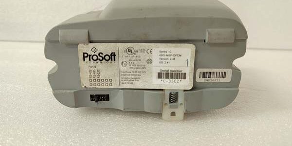
Component Snapshot At-a-Glance
- Model: 4301-MBP-DFCM
- Alt. P/N: No cross-reference factory alternate part number
- Product Series: ProSoft 4300 Industrial Protocol Gateway Series
- Hardware Type: Standalone DIN rail mount Modbus Plus (MBP) ↔ DF1 serial conversion gateway
- Key Feature: Independently configurable Master/Slave mode on both MBP bus and DF1 serial port
- Primary Field Use: Bridge legacy Allen‑Bradley Modbus Plus PLC racks to DF1 serial drives, remote RTUs and SCADA panels
Hard-Numbers: Technical Specifications
- Protocol Support: Modbus Plus (MBP), DF1 Full Duplex/Half Duplex (Master/Slave selectable)
- Port Count: 1 DB9-F Modbus Plus port, 1 terminal block RS422/485 DF1 serial port
- Baud/Data Rate: MBP fixed 1 Mbps; DF1 adjustable 300–19200 baud
- Operating Temperature: -20 °C to +60 °C (derate to +50 °C in sealed unventilated cabinets)
- Storage Temperature: -40 °C to +85 °C
- Isolation Rating: 1500 VAC galvanic isolation separating MBP backplane circuit and DF1 serial field wiring
- Power Draw: Typical 6.8 W, max 8.2 W; 24 VDC operating range 10–28 VDC
- Mount Format: Standard 35 mm DIN rail mount
- Unit Dimensions: 110 mm H × 55 mm W × 130 mm D
- Weight: 0.38 kg
- Ingress Protection: IP20, indoor control cabinet only
- Bus Capacity: Supports up to 32 Modbus Plus nodes; DF1 port handles maximum 31 serial slave devices
The Real-World Problem It Solves
Legacy Allen‑Bradley Modbus Plus hardware lacks native DF1 serial communication. Plant crews previously stacked separate serial communication cards, wasting critical rack DIN rail space and adding extra power load. Unconverted DF1 field devices cannot exchange real-time tags with Modbus Plus PLC logic, forcing manual log entry and blind process control.
Where you’ll typically find it:
- Oil refinery pump MCC racks linking Modbus Plus PLCs to DF1 soft starters and compressors
- Coal power plant ash handling panels connecting legacy Modbus Plus controllers to DF1 flow transmitters
- Water treatment facility SCADA cabinets bridging old PLC5 MBP racks to DF1 remote tank level RTUs
Bottom-line value statement: Single DIN rail unit eliminates extra communication cards and enables bidirectional tag transfer between Modbus Plus and DF1 networks without custom ladder logic workarounds.
Hardware Architecture & Under-the-Hood Logic
This gateway runs a dedicated independent communication processor, no host PLC scan cycle load is consumed for protocol translation. Isolation transformers block ground loop transients from long DF1 field wiring runs.
- 24 VDC cabinet power feeds isolated internal regulation circuits for MBP and DF1 processing subsystems
- Modbus Plus DB9 port synchronizes cyclic tag read/write data with all MBP network PLC nodes at fixed 1 Mbps speed
- Onboard protocol processor maps Modbus Plus register addresses to DF1 file registers with user-defined offset tables
- DF1 RS422/485 terminal block transmits translated data to serial field devices, supporting half/full duplex wiring modes
- Front-panel LED status lights track MBP bus health, DF1 frame activity, power fault and parity/CRC error counts
- Non-volatile local memory stores all mapping configuration; no PLC program re-download required after power cycle
Field Service Pitfalls: What Rookies Get Wrong
Missing 120Ω Termination Resistor on DF1 RS485 Bus Ends
New techs omit terminating resistors at the farthest DF1 slave and gateway terminals. Signal reflection creates random DF1 timeouts that spike during motor VFD switching events.
- Field Rule: Install factory 120Ω resistors at only the two physical endpoints of every DF1 trunk line; remove resistors on intermediate taps.
Cross‑Wiring DF1 Half Duplex A/B Signal Lines
Junior engineers swap DF1 TX/RX A and B terminals on the gateway block. No data frames pass between gateway and serial slaves, even with matching baud/parity settings.
- Quick Fix: Label DF1 A/B wiring at both gateway and slave ends; cross-check pinout against unit side sticker before power restoration.
Mismatched DF1 Serial Parameters Between Gateway and Field Devices
Field crews set gateway DF1 parity/stop bits different from connected soft starters or RTUs. Constant framing and CRC error alarms flood diagnostic logs with zero valid tag reads.
- Field Rule: Standardize baud rate, parity and stop bits across all DF1 bus devices; run gateway diagnostic counter reset to confirm zero frame faults post-setup.
Commercial Availability & Pricing Note
Please note: The listed price is for reference only and is not binding. Final pricing and terms are subject to negotiation based on current market conditions and availability.




