
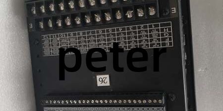
Component Snapshot At-a-Glance
- Model
- Alt. P/N: SR469-CASE (matching panel enclosure)
- Product Series: GE Multilin 469 Motor Management Relay
- Hardware Type: Microprocessor-based motor protective & monitoring relay
- Key Feature: Low (LO) 20–48 VAC / 24–60 VDC control power, built-in 4-channel 4–20mA analog outputs
- Primary Field Use: Full protection, thermal modeling and real-time metering for medium/high horsepower industrial motors
Hard-Numbers: Technical Specifications
- Protocol Support: Modbus RTU (RS485), local EnerVista via front RS232
- Port Count: 1 front-panel RS232, 2 rear isolated RS485 bus ports
- Baud/Data Rate: RS232 fixed 9600 baud; RS485 1200–19200 baud adjustable
- Operating Temperature: -20 °C to +60 °C (no conformal coating; avoid high humidity corrosive cabinets)
- Storage Temperature: -40 °C to +85 °C
- Isolation Rating: 1000 VAC isolation between CT/VT inputs, comms and control power
- Power Draw: Typical 25 VA, maximum 45 VA
- Control Power Range: 20–48 VAC (48–62 Hz) / 24–60 VDC (LO variant spec)
- Analog Outputs: 4 x 4–20mA isolated AO for motor current, temperature, power transmission to PLC/DCS
- RTD Support: 3-wire 100Ω Pt, 100Ω Ni, 120Ω Ni, 10Ω Cu stator bearing temperature sensing
- Output Relays: 6 Form-C dry contacts (1 failsafe service fault relay, 5 configurable trip/alarm relays)
- Ingress Protection: IP20 front panel, panel cutout mount only
- Event Memory: Non-volatile storage for 1024 fault & sequence-of-events records
The Real-World Problem It Solves
Basic overcurrent relays only trip on overamperage, lacking thermal modeling, RTD temperature tracking and motor imbalance logic. Unmonitored stator heat, broken rotor bars and phase unbalance burn large process motors, triggering multi-hour downtime and expensive winding rewinds. Older single-point relays cannot push live motor metrics to plant DCS, forcing manual round-robin inspections.
Where you’ll typically find it:
- Refinery pump and compressor MCC cabinets for 50–200HP process drive motors
- Thermal power plant forced draft / induced draft fan motor control buckets
- Pulp mill digester feed and large extruder motor protection panels
Bottom-line value statement: All-in-one thermal, electrical and mechanical motor fault detection plus native analog output streamlines DCS integration and cuts unplanned motor failure downtime.
Hardware Architecture & Under-the-Hood Logic
This unit runs a dedicated 32-bit industrial processor independent of upstream PLCs; CT secondary, RTD field wiring and communication circuits carry galvanic isolation to block ground loop noise and surge damage. It mounts directly to standard MCC panel cutouts without DIN rail adapters.
- Low-voltage LO control power rectifies and filters incoming 24–60 VDC / 20–48 VAC to supply core CPU and relay drive circuits
- CT/VT secondary inputs sample three-phase current, voltage and ground fault current at sub-millisecond scan intervals
- RTD analog front-end converts stator/bearing resistance readings to temperature values for dynamic thermal model calculation
- Onboard logic executes 15 standard overload curves, unbalance, stall, reverse power and broken rotor bar protection algorithms
- Four 4–20mA analog output stages scale measured kW, current, temperature and thermal capacity for wired DCS tags
- Dual rear RS485 Modbus links broadcast metering and fault logs to plant SCADA; front RS232 port enables local EnerVista setpoint upload/download
- Six Form-C relay contacts assert trip, alarm or motor block-start signals to breaker control and interlock logic
Field Service Pitfalls: What Rookies Get Wrong
Mismatched LO Control Power Supply Ranges
New technicians swap in SR469-P5-HI high-voltage power variants without cross-checking cabinet control voltage. 120VAC fed to LO 24–48V unit instantly fries internal power regulation circuits.
- Field Rule: Label MCC control power voltage on every relay door; only P5-LO units connect to 20–48 VAC / 24–60 VDC control sources.
Unshielded RS485 Wiring Run Parallel With VFD Load Cables
Junior crews route Modbus trunk alongside variable frequency drive output cables. High-frequency switching noise creates cyclic Modbus timeouts, DCS motor tag freeze and missed fault alarms.
- Quick Fix: Separate twisted shielded cable from VFD power runs by minimum 30cm; single-point shield ground at relay rear terminal block.
Ignoring RTD 3-Wire Lead Resistance Calibration
Field crews install long RTD extension wires without running lead-resistance trim in EnerVista. Displayed stator temperature drifts 10–30°C high, causing false overtemperature trips.
- Field Rule: Complete RTD wire resistance calibration after every sensor cable pull or terminal re-termination; verify live temperature readout against handheld meter.
Commercial Availability & Pricing Note
Please note: The listed price is for reference only and is not binding. Final pricing and terms are subject to negotiation based on current market conditions and availability.




