")
Component Snapshot At-a-Glance
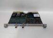
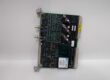
- Model: ALSTOM 43297029, labeled UTILITY MODUL
- Alt. P/N: No direct factory cross-revision part number; no drop-in functional substitute without rack logic modification
- Product Series: ALSPA C80 / HPC VME turbine & generator control rack peripheral utility board
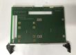
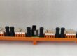
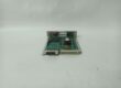
- Hardware Type: Single-height VME plug-in PCB, front panel DB9 serial port, multi-channel status LED array, three onboard signal relay banks, gold-plated rear VME edge connector
- Key Feature: Combined isolated serial communication port + rack auxiliary power filtering + local fault relay flag outputs for turbine supervisory signals
- Primary Field Use: Provide local RS232/RS485 serial access for on-site HMI/laptop commissioning, filter noisy backplane 24V logic power, and buffer hardwired fault alarm contact outputs to plant annunciator panels.
Hard-Numbers: Technical Specifications
- Protocol Support: RS232, ALSPA proprietary serial service protocol, half-duplex RS485 secondary bus
- Port Count: 1 x DB9 front-panel serial port, 3 x isolated relay dry contact output banks
- Baud/Data Rate: Fixed 9600bps service baud rate, VME backplane 10ms data refresh cycle
- Operating Temperature: 0°C to +60°C cabinet operational; -40°C to +85°C storage
- Isolation Rating: 1500Vrms opto-isolation between serial field port and VME backplane logic
- Power Draw: 3.8W total module consumption at nominal 24VDC rack input
- Main Input Power: 18–36VDC station battery, nominal 24VDC VME backplane feed
- Relay Contact Rating: 250VAC / 30VDC, 2A resistive fault alarm dry contacts
- EMC Compliance: IEC 61000-6-2 heavy industrial substation surge immunity
- PCB Treatment: Full acrylic anti-sulfur, anti-salt fog conformal coating
- Physical Weight: 0.48kg single VME slot form factor
The Real-World Problem It Solves
Without this dedicated utility board, technicians must run long shielded serial cables from the main CPU card out to cabinet door terminals for commissioning. Long cable runs introduce EMI noise that corrupts service upload/download sessions during breaker switching transients.Separate external alarm relay terminal blocks add extra wiring splices that corrode and open in high-heat turbine cabinet environments; this board integrates all fault flag relay outputs in one slot.Where you’ll typically find it:
- Steam/gas turbine governor ALSPA C80/HPC VME control racks for on-site commissioning access
- Fossil power plant generator excitation unit cabinets wired to plant annunciator alarm panels
- Refinery large compressor unit turbine supervisory control cubiclesThis single-slot VME board eliminates long CPU serial cable runs and external alarm relay hardware, cutting cabinet wiring and field commissioning downtime.
Hardware Architecture & Under-the-Hood Logic
This board has no dedicated main processing DSP; it acts as a passive isolated signal bridge between the VME backplane CPU bus, local front serial port, and hardwired plant alarm circuits. All signal conversion and power filtering runs on discrete analog and optocoupler circuits.
- Unfiltered 24VDC backplane power enters multi-stage LC EMI filter network to strip VFD and breaker switching noise before feeding onboard serial transceivers and relay coils.
- VME backplane fault status registers pass through opto-isolation barrier to drive three independent signal relay banks for annunciator alarm outputs.
- Front DB9 serial port transceiver uses separate opto-isolation to break ground loops between a field service laptop and rack control ground, blocking common-mode voltage skew.
- Front panel LED bank directly mirrors backplane power status, serial port activity, and each relay bank energized state for fast visual troubleshooting without workstation access.
- Rear gold-plated VME edge connector pulls serial command data and fault register status from the rack CPU, no independent data processing logic on the utility module itself.
Field Service Pitfalls: What Rookies Get Wrong
Hot-Swapping Module While Serial Laptop / Alarm Wiring Remains Live
New techs pull the VME card while a commissioning laptop is plugged into the DB9 port or alarm wiring connected. Sudden open-circuit transients surge back through the VME backplane, corrupting CPU memory registers and triggering unplanned turbine interlock trips.Quick Fix: Disconnect front serial cable and de-energize all external alarm wiring at cabinet terminal blocks before extracting the 43297029 module.
Running Unshielded Serial Patch Cables Parallel To Rack DC Power Harnesses
Junior wiring crews use cheap unshielded RS232 cables for on-site commissioning, routed alongside 24V power supply wiring. Switch-mode EMI distorts serial data frames, firmware uploads fail mid-transfer and corrupt turbine control logic.Field Rule: Only shielded twisted-pair serial cables allowed for front DB9 port connections; route all serial wiring in dedicated signal trays separated from DC power harnesses, single-point shield ground at the cabinet terminal strip only.
Overloading Onboard Relay Outputs With Large Auxiliary Relay Coils
Rookies wire heavy cabinet annunciator relay coils directly to the board’s dry contact terminals. Contact current exceeds the 2A rated limit, burning internal relay contact surfaces and permanently disabling fault alarm signaling.Field Rule: All external alarm loads must use intermediate auxiliary relays to buffer current; never connect coils drawing over 0.5A directly to the 43297029 relay terminals.
Commercial Availability & Pricing Note
Please note: The listed price is for reference only and is not binding. Final pricing and terms are subject to negotiation based on current market conditions and availability.