")
Component Snapshot At-a-Glance
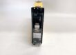
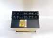
- Model: MCGG52H1CB0753C
- Manufacturer: GEC ALSTHOM (Later acquired by Schneider Electric)
- Alt P/N: MCGG22D1CB0753C (Low-set only, no instantaneous high-set); MCGG62N1CB0753F (Extended curve variant, pinout incompatible)
- Product Series: MCGG (Microprocessor Controlled Generalized Gear) numerical protection relay series
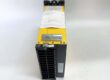
- Hardware Type: Draw-out rack-mount numerical overcurrent & earth fault protection relay, full withdrawable plug-in chassis
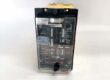
- Key Feature: 3-phase IDMT phase overcurrent + earth fault (51/51N) + H high-set instantaneous fault element, switch-selectable IEC/BS inverse time curves, front panel DIP switch setting, multi-status fault LED indicators
- Primary Field Use: Medium voltage feeder, large induction motor, distribution transformer, auxiliary generator backup protection; clears phase short, overload and earth fault faults in power plants, refinery substation MCC rooms.
Hard-Numbers: Technical Specifications
- Protocol Support: Dry contact fault trip/alarm outputs; optional auxiliary serial communication for SCADA logging
- CT Secondary Rating: Standard 1A secondary current input
- Operating Frequency: 50 / 60Hz universal compatible
- Auxiliary Supply: Wide range DC 48–125V control power
- Operating Temperature: -10°C ~ +60°C cabinet operational; -40°C ~ +85°C storage
- Isolation Rating: 2000Vrms dielectric withstand between CT input circuits and trip output contacts
- Current Setting Range: 0.05×In ~ 2.4×In adjustable via front DIP switches, 0.05A step resolution
- Time Multiplier: 0.05 ~ 1.0 full range for IDMT curve delay
- High-Set Instantaneous Element (H variant): 2.5 ~ 20×In instantaneous trip for severe short-circuit faults
- Available Curve Types: BS142 / IEC 60255 standard inverse curves (Standard Inverse, Very Inverse, Extremely Inverse, Long Time Inverse)
- Fault Reset Ratio: High reset ratio to avoid nuisance reclosing after transient faults
- Output Contacts: Multiple heavy-duty trip relay contacts for breaker trip, fault alarm, remote SCADA indication
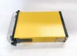
- Mechanical Spec: Draw-out yellow aluminum chassis, transparent front protective cover, standard 19-inch substation rack mounting
- Physical Weight: ~5.2kg complete relay unit
- Certifications: CE, IEC 60255 power protection standard compliant
The Real-World Problem It Solves
Electromechanical induction disc relays drift calibration over years; temperature and vibration shift trip curves, causing either delayed fault clearing or unnecessary nuisance breaker trips.Separate standalone instantaneous overcurrent relays add extra rack slots, additional CT wiring and maintenance calibration points; MCGG52H1 integrates inverse time overload + fast high-set short circuit + earth fault all in one unit.Generic protection relays lack curve selection matching local grid BS/IEC standards; mis-matched time coordination creates selectivity failure, cascading multiple feeders out during single bus fault.Without dedicated earth fault 51N element, high-resistance ground faults go undetected, slowly burning transformer/motor winding insulation until catastrophic equipment failure occurs.Where you’ll typically find it:
- Fossil power plant auxiliary medium voltage feeder & boiler large motor protection panels
- Refinery & petrochemical substation MCC rooms for pump/compressor medium voltage motor backup protection
- Urban distribution substation transformer secondary overcurrent & earth fault backup protection
- Small industrial generator auxiliary backup protection for stator overload & ground fault
This all-in-one numerical IDMT relay eliminates multiple discrete protection devices, delivers configurable grid-standard time coordination, adds fast instantaneous short-circuit clearing and sensitive earth fault detection to prevent costly rotating machine & transformer damage.
Hardware Architecture & Under-the-Hood Logic
This relay uses dedicated analog sampling front-end + fixed function protection logic hardware (early microprocessor numerical platform, no user programmable logic).
- Three-phase CT secondary 1A current signals feed isolated analog sampling circuits, separate dedicated earth fault residual current input.
- On-board analog-to-digital converters continuously sample RMS current values, compare against DIP-switch set pickup thresholds for phase & earth fault elements.
- Four selectable inverse time curve algorithms calculate trip delay proportional to fault magnitude; higher fault current = shorter trip time.
- Independent H high-set instantaneous element bypasses IDMT delay, triggers immediate breaker trip for severe bolted short-circuit faults above set multiple of rated current.
- Dedicated LED status indicators for: Phase Fault, Earth Fault, Instantaneous High-Set Trip, Relay Healthy, Auxiliary Power OK, Trip Contact Operated.
- Heavy-duty isolated relay output contacts energize circuit breaker trip coil and remote fault alarm signals to plant DCS/SCADA system.
- Draw-out chassis design allows full relay removal without disconnecting CT secondary wiring; built-in CT short-circuit terminals to prevent open CT dangerous high voltage during maintenance swap-out.
Field Service Pitfalls: What Rookies Get Wrong
Incorrect DIP Switch Curve Selection Mismatched To Grid Coordination Scheme
New techs randomly select inverse curve during spare replacement without cross-checking substation coordination drawings. Curve mismatch breaks selectivity; upstream & downstream breakers trip simultaneously during feeder fault, causing wide plant power loss.Field Rule: Record curve, pickup current, time multiplier and high-set value on relay door label after every setting change; cross-verify coordination curve sheet before returning relay online.
Forgetting CT Short Circuit Jumpers When Withdrawing Relay
Apprentices pull the MCGG52H1 unit out without installing CT shorting links on the rack base. Open CT secondary generates thousands of volts dangerous surge, damaging relay sampling hardware and creating lethal cabinet shock hazard.Quick Fix: Always install factory CT short-circuit jumpers on rack terminal block before withdrawing draw-out relay chassis for maintenance or spare swap.
Overlooking Auxiliary DC Supply Voltage Mismatch
Crews install unit on 220VDC control circuit without verifying relay 48–125VDC rated auxiliary range. Overvoltage burns internal relay power supply board, unit locks permanent fault state and loses all protection functionality.Field Rule: Confirm cabinet auxiliary DC voltage falls within 48–125V range before energizing MCGG52H1CB0753C relay; isolate incompatible high DC supply circuits.
Mixing MCGG52 Non-H Variant Spare Units In Fault Critical Feeder Panels
Technicians substitute MCGG52 base model (no instantaneous high-set element) to save spare stock. Severe bolted short-circuit faults clear slowly via long IDMT delay, massive through-fault current damages transformer & motor windings.Field Rule: MCGG52H with instantaneous high-set element mandatory for all medium voltage motor & transformer feeders; segregate H / non-H relay spares in clearly labeled storage bins.
Commercial Availability & Pricing Note
Please note: The listed price is for reference only and is not binding. Final pricing and terms are subject to negotiation based on market stock, equipment condition (new/refurbished) and order quantity.