
")
Component Snapshot At-a-Glance
- Model: FCP280; primary factory marking RH924YA
- Alt. P/N: RH101KF, RH101FQ (alternate hardware revision variants)
- Product Series: EcoStruxure Foxboro I/A Series Modern DCS Platform
- Hardware Type: Field-mounted rackable redundant DCS field control processor, FBM backplane master host
- Key Feature: Bit-for-bit cross-check redundant pair logic with <100ms bumpless automatic failover
- Primary Field Use: Executes PID, sequential logic & safety interlocks while polling mixed 100/200-series FBM field I/O modules across 4 independent fieldbus buses
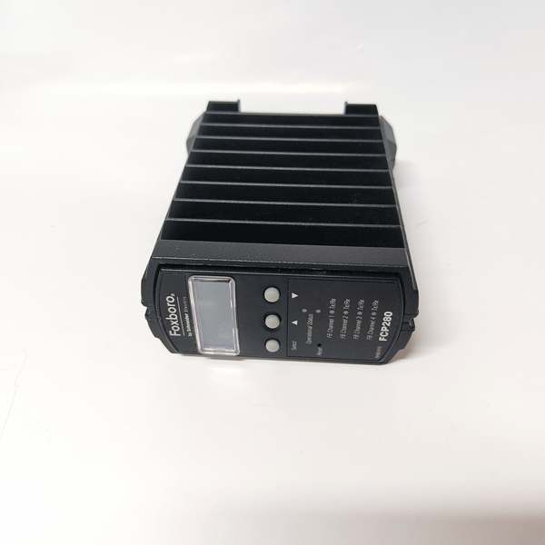
Foxboro FCP280
Hard-Numbers: Technical Specifications
- Protocol Support: 2Mbps/268kbps HDLC FBM Fieldbus, 100Mbps Mesh Ethernet, Modbus TCP, OPC UA
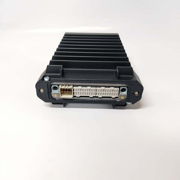
- Port Count: 2x copper/fiber Ethernet uplinks, 4 independent HDLC PIO fieldbus rear bus ports, front LCD debug interface
- Baud/Data Rate: 2Mbps for 200-series FBM; 268kbps fixed for legacy 100-series FBM modules
- Operating Temperature: -40°C ~ +70°C continuous cabinet ambient, G3 corrosive environment rated
- Isolation Rating: 2000VDC galvanic isolation between fieldbus circuits and internal CPU power rail
- Power Draw: 11W nominal single unit; max 15W full load @ 24VDC SELV rack feed
- Max FBM Capacity: Up to 128 mixed FBMs (max 64 units of older 100-series FBM) across four fieldbus branches
- Onboard Memory: 128MB ECC SDRAM, 128MB industrial flash storage; 500MHz ARM SOC core
- Cert Rating: IEC61508 SIL2 functional safety certified, ATEX/UL approved for hazardous area cabinet mount
The Real-World Problem It Solves
Older CP60/CP50 legacy controllers cap out at 32 local FBMs and lack native online firmware upgrade, forcing full rack shutdown for OS flashes and triggering unplanned process trips mid-production. Non-redundant single CPU setups drop entire control loops on component failure, costing refining and power sites costly unplanned downtime.Where you’ll typically find it:
- Petrochemical distillation column DCS cabinets running cascade temperature/pressure closed-loop control
- Coal power boiler feedwater & furnace safety interlock rack assemblies replacing aging I/A classic CP hardware
- Onshore gas compressor skid DCS enclosures bridging field Modbus instruments to central plant Mesh network
Built-in OLUG online firmware update plus expanded FBM count eliminates process downtime during controller maintenance and reduces auxiliary expansion rack count on site.
Hardware Architecture & Under-the-Hood Logic
This die-cast aluminum housed controller splits internal PCB into isolated CPU core, Ethernet PHY and four independent fieldbus transceiver circuits; redundant paired FCP280s sync full runtime database via proprietary inter-board sync bus without shared ground paths.
- Rear terminal block draws regulated redundant 24VDC rack power to isolated onboard switching power supply.
- ARM SOC loads stored control logic from nonvolatile flash and runs continuous PID/sequence/interlock calculations with ECC memory error correction.
- Process setpoint data gets framed into HDLC packets and routed across four separate fieldbus channels to attached FBM I/O cards.
- Raw field analog/digital data from all FBMs passes isolation barrier before updating local real-time process database.
- Front panel LCD displays run status, redundancy role, bus fault codes for quick on-site diagnostic verification.
Foxboro FCP280
Field Service Pitfalls: What Rookies Get Wrong
Uneven FBM Loading Across Four PIO Fieldbus Ports
New tech stacks >40 FBM modules onto a single bus port; bus bandwidth overload triggers intermittent random FBM dropouts and recurring FCP FAULT alarms.
- Field Rule: Cap each individual fieldbus branch at 30 FBM max, split surplus I/O across remaining unused PIO ports.
Shared Single Power Feed For Redundant FCP Pair
Technician wires both active/standby onto identical 24VDC circuit; single power supply fault takes out entire redundant controller pair simultaneously.
- Quick Fix: Route primary/backup FCP power from two separate isolated rack DC supply feeds per site wiring specs.
Run Fieldbus Cable Parallel With 3-phase VFD Power Conduit
Improper tray routing lays HDLC bus wiring next to variable frequency drive high-current cabling; radiated EMI corrupts bus frames leading to sporadic Modbus/FBM communication timeout faults.
- Field Rule: Use double-shielded twisted pair fieldbus cable, separate power/data wiring trays with minimum 12cm vertical clearance.
Commercial Availability & Pricing Note
Please note: The listed price is for reference only and is not binding. Final pricing and terms are subject to negotiation based on current market conditions and availability.


